The 3G4G Blog
Latest news and information on 3G, 4G, 5G wireless and technologies in general.
- 3G4G Homepage
- Telecoms Infrastructure Blog
- Operator Watch Blog
- Connectivity Technology
- 5G Training
- 6G Training
- Private Networks Technology


Friday 23 October 2020
- Positioning Techniques for 5G NR in 3GPP Release-16
I realised that I have not looked at Positioning techniques a lot in our blogs so this one should be a good summary of the latest positioning techniques in 5G.
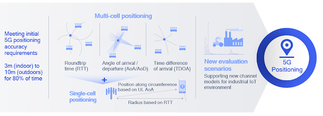
Release-15 NR provides support for RAT-independent positioning techniques and Observed Time Difference Of Arrival (OTDOA) on LTE carriers. Release 16 extends NR to provide native positioning support by introducing RAT-dependent positioning schemes. These support regulatory and commercial use cases with more stringent requirements on latency and accuracy of positioning.25 NR enhanced capabilities provide valuable, enhanced location capabilities. Location accuracy and latency of positioning schemes improve by using wide signal bandwidth in FR1 and FR2. Furthermore, new schemes based on angular/spatial domain are developed to mitigate synchronization errors by exploiting massive antenna systems.
The positioning requirements for regulatory (e.g. E911) and commercial applications are described in 3GPP TR 38.855. For regulatory use cases, the following are the minimum performance requirements:
- Horizontal positioning accuracy better than 50 meters for 80% of the UEs.
- Vertical positioning accuracy better than 5 meters for 80% of the UEs.
- End-to-end latency less than 30 seconds.
For commercial use cases, for which the positioning requirements are more stringent, the following are the starting-point performance targets
- Horizontal positioning accuracy better than 3 meters (indoors) and 10 meters (outdoors) for 80% of the UEs.
- Vertical positioning accuracy better than 3 meters (indoors and outdoors) for 80% of the UEs.
- End-to-end latency less than 1 second.
Figure 3.11 above shows the RAT-dependent NR positioning schemes being considered for standardization in Release 16:
- Downlink time difference of arrival (DL-TDOA): A new reference signal known as the positioning reference signal (PRS) is introduced in Release 16 for the UE to perform downlink reference signal time difference (DL RSTD) measurements for each base station’s PRSs. These measurements are reported to the location server.
- Uplink time difference of arrival (UL-TDOA): The Release-16 sounding reference signal (SRS) is enhanced to allow each base station to measure the uplink relative time of arrival (UL-RTOA) and report the measurements to the location server.
- Downlink angle-of-departure (DL-AoD): The UE measures the downlink reference signal receive power (DL RSRP) per beam/gNB. Measurement reports are used to determine the AoD based on UE beam location for each gNB. The location server then uses the AoDs to estimate the UE position.
- Uplink angle-of-arrival (UL-AOA): The gNB measures the angle-of-arrival based on the beam the UE is located in. Measurement reports are sent to the location server.
- Multi-cell round trip time (RTT): The gNB and UE perform Rx-Tx time difference measurement for the signal of each cell. The measurement reports from the UE and gNBs are sent to the location server to determine the round trip time of each cell and derive the UE position.
- Enhanced cell ID (E-CID). This is based on RRM measurements (e.g. DL RSRP) of each gNB at the UE. The measurement reports are sent to the location server.
UE-based measurement reports for positioning:
- Downlink reference signal reference power (DL RSRP) per beam/gNB
- Downlink reference signal time difference (DL RSTD)
- UE RX-TX time difference
gNB-based measurement reports for positioning:
- Uplink angle-of-arrival (UL-AoA)
- Uplink reference-signal receive power (UL-RSRP)
- UL relative time of arrival (UL-RTOA)
- gNB RX-TX time difference
NR adopts a solution similar to that of LTE LPPa for Broadcast Assistance Data Delivery, which provides support for A-GNSS, RTK and OTDOA positioning methods. PPP-PTK positioning will extend LPP A-GNSS assistance data message based on compact “SSR messages” from QZSS interface specifications. UE-based RAT-dependent DL-only positioning techniques are supported, where the positioning estimation will be done at the UE-based on assistance data provided by the location server.

Related Posts :
- Connectivity Technology Blog: 5G Indoor Precise Positioning
- The 3G4G Blog: R&S Webinar on LTE-A Pro and evolution to 5G
2 comments:
Coulde you explain what the negative number of UL-RTOA means? UL-RTOA: The reporting range of UL Relative Time of Arrival (UL-RTOA), as defined in Clause 5.2.2 of TS 38.215 [4], is defined from -985024Tc to +985024×Tc. The reporting resolution is uniform across the reporting range and is defined as T = Tc*2k where k is selected by gNB from the set {0, 1, 2, 3, 4, 5}.
You might want to ask the question in the video on YouTube so someone from R&S team can provide an answer.
Post a Comment
Follow us on LinkedIn!
Pageviews last 30 days, join linkedin group.

Like 3G4G blog
Blog archive.
- ► April (1)
- ► March (1)
- ► February (1)
- ► January (2)
- ► December (2)
- ► November (2)
- ► October (2)
- ► September (1)
- ► August (2)
- ► July (1)
- ► June (1)
- ► May (3)
- ► February (2)
- ► October (3)
- ► September (3)
- ► August (5)
- ► July (3)
- ► June (4)
- ► May (5)
- ► April (3)
- ► March (3)
- ► February (4)
- ► January (4)
- ► December (4)
- ► November (6)
- ► October (4)
- ► September (5)
- ► August (4)
- ► July (4)
- ► June (7)
- ► May (4)
- ► April (2)
- ► March (6)
- ► February (5)
- ► January (5)
- ► December (5)
- Understanding the TCO of a Mobile Network
- Couple of Tutorials on ETSI NFV MANO
- What is Cloud Native and How is it Transforming th...
- Understanding the Dual Active Protocol Stack (DAPS...
- 5G Enhanced URLLC (eURLLC)
- ► September (4)
- ► August (6)
- ► July (6)
- ► June (6)
- ► May (8)
- ► April (8)
- ► February (3)
- ► January (6)
- ► November (4)
- ► October (5)
- ► July (7)
- ► June (5)
- ► April (7)
- ► March (9)
- ► February (6)
- ► December (3)
- ► November (3)
- ► October (6)
- ► September (6)
- ► August (3)
- ► July (5)
- ► April (4)
- ► March (4)
- ► December (8)
- ► November (8)
- ► September (9)
- ► November (5)
- ► January (3)
- ► June (9)
- ► May (6)
- ► April (6)
- ► January (8)
- ► October (9)
- ► September (7)
- ► August (10)
- ► July (15)
- ► May (10)
- ► March (8)
- ► February (11)
- ► January (11)
- ► December (19)
- ► November (16)
- ► October (21)
- ► September (16)
- ► August (15)
- ► July (19)
- ► June (17)
- ► May (20)
- ► April (25)
- ► March (26)
- ► February (15)
- ► January (15)
- ► December (13)
- ► November (24)
- ► October (23)
- ► September (18)
- ► August (20)
- ► July (24)
- ► June (15)
- ► May (17)
- ► April (15)
- ► March (19)
- ► February (20)
- ► January (20)
- ► December (20)
- ► November (22)
- ► October (16)
- ► August (27)
- ► July (26)
- ► June (24)
- ► May (26)
- ► March (22)
- ► February (22)
- ► January (23)
- ► December (17)
- ► November (20)
- ► October (20)
- ► September (28)
- ► August (25)
- ► July (33)
- ► June (38)
- ► May (39)
- ► April (36)
- ► March (27)
- ► January (33)
- ► December (30)
- ► November (19)
- ► October (22)
- ► September (21)
- ► August (18)
- ► July (18)
- ► June (16)
- ► May (16)
- ► April (20)
- ► March (17)
- ► December (10)
- ► October (10)
- ► September (13)
- ► July (20)
- ► May (18)
- (e)MBMS (44)
- 5G Americas (20)
- 5G Non-Stand Alone (4)
- 5G NR-Unlicensed (1)
- 5G Stand-Alone (13)
- 5G-ACIA (5)
- 5G-Advanced (15)
- 802.11ac (1)
- 802.11ax (3)
- 802.11n (3)
- 802.11p (1)
- 802.16n (1)
- ABI Research (2)
- Ad-Hoc Networks (5)
- Advertisement (12)
- Africa (19)
- Airspan (1)
- Alcatel-Lucent (43)
- Analysys Mason (2)
- Android (15)
- Anomaly Detection (1)
- Anritsu (8)
- Antennas (42)
- Anzafrika (1)
- Appledore Research (1)
- Apps Adult (5)
- Apps Alarm (1)
- Apps Art (1)
- Apps Banking (3)
- Apps Barcodes (3)
- Apps Books (2)
- Apps Broadcast (5)
- Apps Browsing (6)
- Apps Camera (14)
- Apps Car (4)
- Apps Comics (1)
- Apps Content (4)
- Apps Dating (3)
- Apps Education (1)
- Apps Family (1)
- Apps Financial (3)
- Apps Games (3)
- Apps Healthcare (14)
- Apps Keeping Fit (2)
- Apps Location (8)
- Apps Love Detector (1)
- Apps M-Commerce (3)
- Apps Messaging (5)
- Apps Military (1)
- Apps MMS (4)
- Apps Mobile Payments (3)
- Apps Music (2)
- Apps News (1)
- Apps Plane (1)
- Apps Recognition (1)
- Apps Ringtones (1)
- Apps Scanners (1)
- Apps Search (6)
- Apps Security (13)
- Apps SMS (37)
- Apps SocNet (5)
- Apps Speech Recognition (2)
- Apps Speech Translation (2)
- Apps Testing (1)
- Apps USSD (1)
- Apps Video Calling (3)
- Apps Video Sharing (3)
- Apps Video Streaming (5)
- Apps Voicemail (1)
- Apps Wallet (2)
- Apps Wireless Memory (1)
- April Fools' Day (7)
- AR / VR / MR / XR (16)
- Arthur D Little (1)
- Artificial Intelligence (18)
- AT&T (14)
- Austria (1)
- Awards and Prizes (7)
- Backhaul (37)
- Base Station (6)
- Battery (18)
- Big Data (7)
- Billing (10)
- Blackberry (9)
- Blockchain (1)
- Bluetooth (20)
- Broadband (57)
- Broadband Forum (1)
- Broadcom (3)
- Browsers (4)
- BT / EE (26)
- Buildings and Materials (3)
- Cambridge Wireless (CW) (86)
- Camera (17)
- Capex and Opex (2)
- Carrier Aggregation (39)
- Case Studies (10)
- CCS Insight (1)
- CDMA2000 (1)
- cell trace (1)
- Cellular IoT (9)
- Change of gNB-CU-UP (1)
- China Mobile (24)
- China Telecom (5)
- China Unicom (2)
- Cloud Computing (7)
- Codecs (10)
- Cognitive Computing (1)
- Cognitive radio (10)
- Concept Mobile (28)
- Conditional Handover (1)
- Conferences and Events (106)
- Connected World (24)
- Connection Release (1)
- Converged Devices (2)
- COVID-19 (1)
- Data Offload (11)
- Data Speeds (12)
- Data Traffic Management (31)
- Democratic Republic of the Congo (1)
- Densification (1)
- Deployment (26)
- Deutsche Telekom (16)
- Diameter (12)
- Diversity (1)
- Drones & UAVs (3)
- Dual Connectivity (DC) (3)
- e-tumba (1)
- Edge and Fog Computing (13)
- Emergency (35)
- Energy Consumption and Savings (5)
- Environment and Green Issues (21)
- EPS Fallback (2)
- Ericsson (87)
- Europe (12)
- Event A6 (1)
- Far EasTone (1)
- Fast Dormancy (2)
- Femtocell Applications (12)
- Femtocells (154)
- Fibre Optics (11)
- Finland (2)
- Firecell (1)
- Firefox OS (3)
- Fixed Network (2)
- Fixed Wireless Access (2)
- FlashLinq (4)
- FOKUS FUSECO Forum (9)
- Forecast (12)
- Forum Oxford (2)
- Free France (1)
- Future Networks (23)
- Future Technologies (102)
- General (42)
- General Motors (1)
- Geolocation (1)
- Germany (2)
- Google (36)
- Handover (7)
- Handovers (23)
- Health (11)
- HetNets (28)
- High Frequency Technologies (4)
- History (7)
- Hong Kong (2)
- HSDPA Mobile (2)
- Huawei (59)
- IDATE Digiworld (5)
- IMS Services (12)
- IMT-2020 (10)
- IMT-Advanced (17)
- Indoor Connectivity (1)
- Industrial Automation (1)
- Industry 4.0 (3)
- Inflight Communication (2)
- Infrastructure Vendor (12)
- inter-gNB-CU Handover (2)
- inter-gNB-DU Handover (1)
- Interdigital (15)
- Interference Avoidance (6)
- Interference Management (10)
- Internet of Things (68)
- intra-gNB Handover (2)
- iPhone (30)
- Iskratel (1)
- Keysight (Agilent) (19)
- Kids Mobile (3)
- Laptops (5)
- Latin America (4)
- Lawful Intercept (3)
- Layer 2 Measurements (1)
- Licensing (5)
- Linux Foundation (1)
- LoRaWAN (10)
- LTE & 5G World Series (163)
- LTE Voice and SMS Issues (51)
- LTE-Advanced (97)
- LTE-Advanced Pro (8)
- Luxury Mobile (2)
- Machine Learning (11)
- Mans LMT (1)
- Maritime Communications (1)
- Market Analysis (30)
- Marketing (4)
- Mavenir (1)
- MediaFLO (5)
- MediaTek (2)
- Mesh Technology (4)
- Metaverse (2)
- Metrocell (7)
- Microsoft (6)
- Mindspeed (6)
- Mobile Cloud (5)
- Mobile Data (42)
- Mobile Humour (49)
- Mobile Phones and Devices (226)
- Mobile TV (47)
- Mobile World Congress (46)
- Mobsessed (1)
- Motorola (16)
- Mpirical (9)
- Multi-Band Cell (2)
- Netherlands (1)
- NETSCOUT nGenious Session Analyzer (1)
- Network Analytics (1)
- Network Architecture (129)
- Network Automation (2)
- Network Infrastructure (9)
- Network Optimisation (22)
- Network Sharing (13)
- Network Slicing (16)
- Nigeria (1)
- Nokia Networks (52)
- NTT DoCoMo (73)
- Ooredoo (2)
- Open RAN (19)
- Open Source (4)
- Operators (61)
- Orange (20)
- Parallel Wireless (16)
- PDN Connections (1)
- PenHertz (1)
- Picocells (9)
- Positioning (3)
- Predictions (6)
- Pricing (8)
- Primary Cell (1)
- Private Networks (10)
- Projectors (3)
- Public Safety Comm (20)
- Push Services (3)
- QoS Flow (2)
- Quad-play (1)
- Qualcomm (94)
- Quantum Technology (4)
- Quintel (2)
- Radio Design (1)
- Radio Link Failure (1)
- Radisys (1)
- Railway Communications (6)
- Rakuten (2)
- RAN Intelligence Controller (1)
- RAN Intelligent Controller (1)
- RAN Sharing (4)
- Receivers (2)
- Red Hat (1)
- Regulations (3)
- Release 10 (69)
- Release 11 (61)
- Release 12 (54)
- Release 13 (28)
- Release 14 (15)
- Release 15 (27)
- Release 16 (47)
- Release 17 (31)
- Release 18 (19)
- Release 19 (3)
- Release 6 (7)
- Release 7 (24)
- Release 8 (67)
- Release 9 (51)
- Reliance Jio (3)
- Religion (2)
- Revenues (11)
- RF Front-End (1)
- Road Safety (2)
- Roaming (23)
- Robert Bosch (1)
- Robotics and Automation (4)
- Rohde and Schwarz (25)
- Rollouts (37)
- RRC Inactive State (5)
- Rural Communications (8)
- Samsung (60)
- Satellite Communications (27)
- SC-FDMA (5)
- Screen and Display (6)
- SDN / NFV (22)
- Secondary Cell (1)
- Security (71)
- Short Range Wireless (7)
- Signalling (105)
- Simulators (10)
- Site Pyo (1)
- Small Cell Forum (18)
- Small Cells (85)
- Smart Farming (1)
- Smart Grids (6)
- Smart Home and Cities (6)
- Smartphones (31)
- Smartwatches (2)
- SmartWear (6)
- Softbank (7)
- Sony Ericsson (10)
- South Korea (19)
- Special Cell (1)
- Spectrum (136)
- Standards (20)
- Stats (181)
- Strategy Analytics (1)
- Switzerland (1)
- Symbian (1)
- Synchronization (4)
- T-Mobile USA (10)
- TCP/IP (29)
- TD-LTE (28)
- TD-SCDMA (13)
- Tech Laws (1)
- Tech Quotes (1)
- Technical Details (248)
- Telefonica (26)
- Telehealth (8)
- Telstra (2)
- Terahertz (1)
- Testing (33)
- Thales Alenia Space (1)
- Three UK (4)
- Timing and Phase (7)
- Top Posts (1)
- Training (18)
- Transforma Insights (2)
- Trends (17)
- Triple-play (2)
- Trivergence (1)
- Turkcell (1)
- Tutorials (22)
- Twitter Discussion (15)
- Ubiquisys (17)
- UE Radio Capability ID (1)
- Underwater Wireless (1)
- United Nations (1)
- Unlicensed LTE (5)
- Use Cases (14)
- User Data Convergence (2)
- User Interface (2)
- Utilities (1)
- Verizon (7)
- Videos (255)
- Vodafone (33)
- Voice Communications (4)
- Voice over New Radio (2)
- Wave by AGC (1)
- White Papers and Reports (88)
- Whitespaces (5)
- Windows Mobile (2)
- WiTricity (3)
- Wray Castle (1)
Google Analytics
- Original Article
- Open access
- Published: 05 September 2022
Performance improvement of 5G positioning utilizing multi-antenna angle measurements
- Wenfei Guo 1 ,
- Yue Deng 1 ,
- Chi Guo ORCID: orcid.org/0000-0003-2022-2121 1 ,
- Shufeng Qi 1 &
- Jingrong Wang 1
Satellite Navigation volume 3 , Article number: 17 ( 2022 ) Cite this article
3531 Accesses
2 Citations
1 Altmetric
Metrics details
Time delay-based the 5th Generation Mobile Communication Technology (5G) positioning is a main method to perform high-precision positioning in Global Navigation Satellite System (GNSS) denied areas. However, in practical applications, the occlusion of signals in a complex environment results in few observable base stations, which affects the reliability and accuracy of positioning. The aim of this study is to improve the performance of the 5G positioning in complex environments with an insufficient number of observable base stations. First, the Angle of Departure (AOD) capability of multi-antennas is integrated into Multi-Round-Trip-Time (Multi-RTT) positioning, establishing a novel 5G RTT/AOD positioning model. Then, the influencing factors of positioning performance, including the Dilution of Precision (DOP) and the accuracy of the AOD measurements, is analyzed. The relationship between DOP and RTT/AOD positioning accuracy is deduced. Afterwards, simulation experiments are performed on 5G positioning with the Multi-RTT and RTT/AOD methods in two scenarios with good and complex environments. The theoretical analysis and experimental results show that 5G positioning with the RTT/AOD method increases the horizontal and vertical accuracies by approximately 25 and 65%, respectively, compared with the Multi-RTT method. The positioning reliability is also greatly improved. The proposed model can well solve the inefficiency of 5G positioning with the RTT method in scenarios where the number of base stations is less than three.
Introduction
In addition to its communication functions, the 5th Generation Mobile Communication Technology (5G) has many excellent features, such as its ultra-dense base stations and the Angle of Departure (AOD) capability of multi-antennas, required for positioning (3GPP TS38.305, 2020 ;3GPP TS 48.455 2019 ). As the communication standard maker, the 3rd Generation Partnership Project (3GPP) has been committed to adding positioning capabilities to the communication standards (Keating et al., 2019 ). In Release 16 TS38.855, 3GPP has defined multiple positioning methods (Liu et al., 2017 ), including Down Link Time Difference of Arrival (DL-TDOA), Up Link Time Difference of Arrival (UL-TDOA), Multi-Round-Trip-Time (Multi-RTT), Down Link Angle of Departure (DL-AOD), Up Link Angle of Arrival (UL-AOA), and Enhanced Cell Identity (E-CID). Among them, time delay and angle are the main signal characteristics used for 5G positioning. The time delay method can achieve better positioning capability (Chaloupka, 2017 ) and is the key to expanding positioning capability from the Second-Generation mobile network or service (2G) to the Fourth-Generation of wireless standards for cellular systems (4G), such as the Observed Time Difference of Arrival (OTDOA) method supported by Idle Periods in Down Link (IPDL) in Code Division Multiple Access 2000 (CDMA2000) and Positioning Reference Signal (PRS) in Long-Term Evolution (LTE). The core objective is to improve the accuracy of time delay observation.
The high-precision positioning based on time delay observations has been widely studied. However, high-precision time delay observations are dependent on the synchronization accuracy of 5G base stations. The realization of sub-meter-level positioning accuracy requires nanosecond time synchronization accuracy (Chaloupka, 2017 ). Considering time synchronization, at least four observable base stations are required for Three Dimensional (3D) positioning using the TOA-based methods. Multi-RTT 3D positioning, which is immune to the influence of time synchronization, requires at least three observable base stations. Yet, the probability of meeting this requirement is quite low in practical applications. In the literature (Dammann et al., 2015 ), the case where at least one of the three base stations is non-line-of-sight is defined as an outage. For three base stations with spacing of 100 m, the probability of the outage is 82.2%.
Given the increasing communication needs and demands, 5G base stations will include a large-scale antenna array in the future to expand the communication capacity with beamforming technology (Wen et al., 2019 ; Wymeersch et al., 2017 ). This innovation will also enable the 5G base stations to have a certain angle measurement capability and realize AOD-based 5G positioning. AOD-based positioning is different from Multi-RTT positioning in two aspects: one is the AOD 3D positioning needs at least two observable base stations, while Multi-RTT positioning three observable base stations. The other is the vertical accuracy is better than the horizontal accuracy in AOD positioning, whereas the horizontal accuracy is better than the vertical accuracy in Multi-RTT positioning. At present, the angle-based positioning algorithms can be divided into three types. One is the iterative least squares algorithm based on Causs-Newton method. This algorithm uses the iterative least squares method with user initial position (Torrieri et al. 1984 ). The model of this algorithm is simple, but greatly affected by the initial position. The second one is an algorithm based on grid matching, which matches the theoretical value of an angle with the measurements at all possible positions and takes the position with the highest matching score as the user position (Cominelli et al., 2019 ). This algorithm is often very time consuming. The third one is the closed-form solution algorithm, that is, positioning is achieved by establishing linear or pseudo-linear equations of angle measurements by using the geometric relationships among angle measurements, user position, and base station position (Wang et al. 2015 ; Monfared et al., 2018 ). This algorithm model is complex, but without iteration and less affected by initial position.
Several scholars carried out the theoretical analysis and experimental verifications of the time delay/angle fusion positioning to improve the positioning reliability and accuracy. Most studies focus on the TOA/AOD fusion positioning instand of RTT/AOD fusion positioning. The former is suffered by the time synchronization between the base stations and users compared to the latter. The research on 5G positioning shows that positioning error below one meter can be achieved with joint TOA and AOD methods (del Peral-Rosado et al., 2016 ). Shahmansoori et al. ( 2017 ) derived the Cramér–Rao Lower Bound (CRLB) for TOA/AOD-based positioning using a single transmitter in the presence of scatters. In terms of experimental methods for 5G positioning, Koivisto et al., ( 2017a , b ; 2018 ) designed a simulation experiment combining AOD and TOA, detailing clock model, channel modelling, and simulation scenario setting. He also proposed a two-stage Extended Kalman Filter scheme to extract observations and estimate position. To analyze positioning performance, Li et al. ( 2018 ) calculated the CRLB with the TOA/AOD method for 2D positioning in the condition of a sufficient number of observable base stations. In addition, some scholars studied the fusion positioning of 5G TOA/AOD and GNSS based on the least squares approach and Helmert variance component estimation, and obtained the positioning results with the accuracy at meter level (Su et al. 2020 ; Sun et al., 2020 ). Compared with the TOA method, the TOA/AOD method can relax the strict time synchronization requirements of the positioning system. However, most of the above studies are experimental for or analyze the positioning performance in the condition of a sufficient number of observable base stations. They also fail to consider the effect of the AOD measurements on the reliability and accuracy of 5G positioning in such environments. In practical applications, especially in complex environments like indoors, the number of available 5G base stations is usually insufficient. Thus, the performance of 5G positioning will be significantly deteriorated.
In this study, the AOD capability of multi-antennas is integrated into 5G Multi-RTT positioning to test its efficiency. The main objective is to improve 5G positioning reliability and accuracy in a complex environment where the number of observable base stations is insufficient. The influence of the AOD measurements on the positioning performance is analyzed theoretically. Then, simulation experiments are carried out in two scenarios with good and poor observation environments, respectively, to compare the differences in the reliability and accuracy of 5G positioning before and after adding the AOD measurements. In this paper, we focus on the positioning rather than signal processing without considering the issues of the Non Line of Sight (NLOS) and multipath propagation of signals.
The remainder of this article is organized as follows. A 5G positioning model integrating the AOD and RTT methods is introduced in Section “ 5G positioning model integrating RTT/AOD ”. The influencing factors of positioning performance, including the Dilution of Precision (DOP) and the accuracy of AOD measurement, are analyzed in Section “ Positioning performance analysis ”. Simulation experiments are conducted in Section “ Experiment and results ” to compare the positioning performances before and after adding the AOD measurements. Finally, the conclusions are provided in Section heading “ Conclusions ”.
5G positioning model integrating RTT/AOD
The basic principle commonly used in 5G positioning is similar to that in GNSS. It measures the distance between a base station and a user with the time delay and calculates the user position by multi-station intersection (Groves, 2015 ). 5G communication system uses Orthogonal Frequency Division Multiplexing (OFDM) signal based on cyclic prefix as 5G communication signal. Likewise, the PRS signal used to generate TOA observations is thus constructed. The PRS signal sequence of the downlink is a pseudo-random sequence generated by a Gold sequence with a length of 31. The user will receive a PRS signal for relevant detection to get the delay information of each base station. Using the up-link TOA \(t_{{\text{up - link}}}^{{{\text{TOA}}}}\) and the down-link TOA \(t_{{\text{down - link}}}^{{{\text{TOA}}}}\) , we can construct the RTT \(t_{{{\text{RTT}}}}\) as follows:
As we can see, \(t_{{{\text{RTT}}}}\) is not affected by the time synchronization in (1). Without considering the NLOS and multipath propagation of the signal, the \(t_{{{\text{RTT}}}}\) between the user and each base station multiplied by the speed of light generates the distance. Assuming that \(\left(x,y,z\right)\) is the coordinates of the user to be estimated, \(\left({x}_{i},{y}_{i},{z}_{i}\right)\) is the coordinates of base station \({s}_{i}\) , and \({t}_{i}\) is the RTT observation between base station \({s}_{i}\) and the user. The distance between the user and base stations can be expressed as
where \(c\) is the speed of light. When the accuracy loss caused by linearization is ignored, the linearized observation equations of Multi-RTTpositioning can be obtained as
where \({\varvec{X}}\) is the state vector, \({\varvec{Z}}\) is the observation vector, \({\varvec{H}}\) is the transition matrix, and \({\varvec{V}}\) is the observation error vector. These variables can be respectively expressed as.
where \(\left({x}_{0},{y}_{0},{z}_{0}\right)\) represents the user’s initial coordinates, and \(\delta {t}_{i}\) is the observation error of time delay. \({l}_{i,3d}\) is the 3D distance between the user’s initial position and base station, which is defined as
Following the observation equation of Multi-RTT positioning, a base station can only provide one RTT observation, and therefore to solve for 3 unknown coordinates at least three base stations are needed.
A 5G positioning model integrating RTT and AOD is proposed to improve the 5G positioning performance in the situation of insufficient base stations. AOD observations are obtained by the channel estimation algorithm using Channel State Information Reference Signal (CSI-RS) and the antenna information of transmitter and receiver. In this model, the azimuth AOD, vertical AOD, and signal propagation delay of 5G signal are expressed as \({\alpha }_{i}\in (-\uppi ,\uppi ]\) , \({\beta }_{i}\in (-\frac{\uppi }{2},\frac{\uppi }{2}]\) , and \({t}_{i}\) , respectively. The relationship among time delay, angle observation, and user’s coordinates can be expressed as.
Following the above equation, one base station can provide three observations. Thus, positioning can be carried out with a single base station. Similarly, the observation equation of RTT/AOD positioning in the form of (3) can be obtained, where the observation vector \({\varvec{Z}}\) , transition matrix \({\varvec{H}}\) , and observation error vector \({\varvec{V}}\) can be respectively expressed as
where \(\updelta {\alpha }_{i}\) and \(\updelta {\beta }_{i}\) indicate the observation errors of the azimuth and vertical angles, respectively. \({l}_{i,2d}\) is the 2D distance between the user’s initial position and base station, which is defined as
In Multi-RTT and RTT/AOD positioning, the weight matrix \(P\) is set as the reciprocal of the variance of the observations. Then the user’s final coordinates \(\left(x,y,z\right)\) can be obtained through the iterative least square estimation as
Positioning performance analysis
In Multi-RTT positioning model, the main factors that affect the positioning performance include the number of base stations, distribution of base stations, and accuracy of observations. Assuming the estimated error of the state vector \({\varvec{X}}\) is \(\Delta {\varvec{X}}\) , after ignoring and simplifying the second-order error term, the relationship between the estimated error \(\Delta {\varvec{X}}\) and the observation error \({\varvec{V}}\) can be obtained as
where \({{\varvec{H}}}_{t}\) is calculated by bringing in the true value of the user’s coordinates in the formula for calculating the transition matrix \({\varvec{H}}\) . The time delay observations are assumed to be independent of each other and satisfy the zero-mean Gaussian distribution with the variance of \({{\sigma }_{t}}^{2}\) . Accordingly, the accuracy of the 3D position estimation based on Multi-RTT positioning Root Mean Square (RMS) \({s}_{\mathrm{RMS}}^{\mathrm{RTT}}\) can be written as
\({d}_{\mathrm{DOP}}=\sqrt{\mathrm{tr}\left\{{\left({{{\varvec{H}}}_{t}}^{\mathrm{T}}{{\varvec{H}}}_{t}\right)}^{-1}\right\}}\) is completely determined by the number of base stations and the geometric relationship between the user and base stations. Thus,
When the accuracy of time delay observation is the same, the smaller the \({d}_{\mathrm{DOP}}\) , the higher the accuracy of position estimation will be.
In RTT/AOD positioning, vector \({\varvec{V}}\) is a column vector composed of angle and time delay observation errors. Assuming that each observation error is independent, the accuracy of the 3D position estimation RMS \({s}_{\mathrm{RMS}}^{\mathrm{RTT}/\mathrm{AOD}}\) can be written as
The weighted matrix \({\varvec{P}}\) in (18) includes time delay accuracy and angle measurement accuracy. Thus, the relationships among \({s}_{\mathrm{RMS}}^{\mathrm{RTT}/\mathrm{AOD}}\) , \({d}_{\mathrm{DOP}}\) , and observation accuracy are no longer linear (Han, 2014 ).
In (16) and (18), the RMS represents the accuracy of the Weighted Least Square (WLS) estimated user’s position. Because WLS estimation belongs to a minimum variance estimation, when the initial coordinates of the user are equal to the true coordinates, the a posteriori estimated variance matrix of WLS is the inverse of the Fisher information matrix, which is consistent with the definition of Cramér-Rao Bound (CRB).
As shown in Section “ Appendix ”, \({s}_{\mathrm{RMS}}^{\mathrm{RTT}/\mathrm{AOD}}\) is smaller than \({s}_{\mathrm{RMS}}^{\mathrm{RTT}}\) . Thus, the addition of AOD improves the accuracy of position estimation. One can see if the accuracy of time delay \({\sigma }_{t}\) and the \({d}_{\mathrm{DOP}}\) are the invariant, the higher the accuracy of angle measurements, the higher the accuracy of position estimation will be.
The addition of AOD reduces the influence of the distribution of base stations on positioning results. In a complex environment, the number of base stations that can be observed by the user is small, and the distribution of base stations is poor. Accordingly, the addition of AOD is conducive to the accuracy and reliability of 5G positioning. The following part will analyze the influence of the AOD on positioning accuracy and reliability.
Influence of AOD on positioning accuracy
The influence of the distribution of base stations on positioning accuracy can be measured by \({d}_{\mathrm{DOP}}\) value. For example, in the 2D Multi-RTT positioning, assuming that the number of base stations is \(N\) , and \(\left(\mathrm{cos}{\theta }_{i},\mathrm{sin}{\theta }_{i}\right),{\theta }_{i}\in (-\uppi ,\uppi ]\) represents the relative position from the \(i\) th base station to the user, then
Taking 3 base station as an example, the connections between base stations and a user divide the space around the user into three sectors with the sector angles denoised as \({\alpha }_{1}\) , \({\alpha }_{2}\) , and \({\alpha }_{3}\) . When \({\alpha }_{1}={\alpha }_{2}=60^\circ ,{\alpha }_{3}=240^\circ\) , or \({\alpha }_{1}={\alpha }_{2}={\alpha }_{3}=120^\circ\) , \({d}_{\mathrm{DOP}}\) has a minimum value \(\frac{2\sqrt{3}}{3}\) , corresponding to the optimal distribution of three base stations, as shown in Fig. 1 .
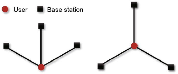
Optimal distribution of three base stations
The positioning accuracy with Multi-RTT and RTT/AOD obtained by the user under the optimal distribution of three base stations (equilateral triangle distribution) and with the accuracy of RTT and AOD measurements being 1 m and 2.5°, respectively, is shown in Fig. 2 , where the red triangles stand for the fixed base stations with the spacing of 100 m between them. The above values are typical for mathematical analysis, but not real in an urban area, even in an UMi scenario. For Multi-RTT positioning and RTT/AOD positioning, the users near a base station can be positioned with an accuracy better than 1.4 m. Compared with the positioning accuracy based on RTT, the area where the accuracy is better than 1.4 m is expanded for RTT/AOD positioning.
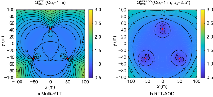
Positioning accuracy in the optimal distribution of three base stations
Influence of AOD on positioning reliability
Generally, 3D positioning involves three unknown parameters. In Multi-RTT positioning, each base station can only provide one RTT observation, and thus at least three base stations are needed. The positioning principle is shown in Fig. 3 (a). In RTT/AOD positioning, a base station provides three observations: distance, vertical angle, and azimuth angle. Therefore, only one base station is enough for positioning, as shown in Fig. 3 (b). The addition of AOD reduces the the minimum number of base stations and can effectively improve the positioning reliability when the number of observable base stations is small.
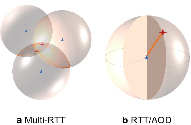
Positioning principle
For the details, refer to Section “ Influence of AOD on positioning accuracy ” When \({\alpha }_{1}={\alpha }_{2}=180^\circ ,{\alpha }_{3}=0^\circ\) or \({\alpha }_{1}=360^\circ ,{\alpha }_{2}={\alpha }_{3}=0^\circ\) , \({d}_{\mathrm{DOP}}\) value is the maximum and approaches infinity, which corresponds to the worst distribution of three base stations, as shown in Fig. 4 .
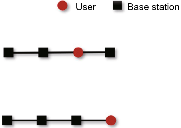
Worst distribution of three base stations
In the worst distribution of the three base stations, the base stations are in line with the user. The accuracy of Multi-RTT positioning and RTT/AOD positioning by users under the worst distribution of the three base stations is shown in Fig. 5 . The user close to the connection of the base stations has poor accuracy in Multi-RTT positioning. Only when the user is far away from the straight line between the base stations vertically can the positioning accuracy of greater than 1.2 m be obtained. In RTT/AOD positioning, the accuracy for the users near the straight line between the base stations has been greatly improved from greater than 10 m to less than 2 m.
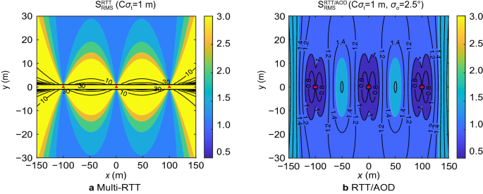
Positioning accuracy in the worst distribution of three base stations
Some conclusions can be drawn below. In the same observation condition, the addition of AOD provides more observations resulting in higher positioning accuracy compared with Multi-RTT positioning. Moreover the addition of AOD reduces the number of base stations, lowers the influence of the poor distribution of base stations on positioning results, and improves the reliability of positioning in poor observation environments.
Experiment and results
The experiment was in the urban environment. To vertify the theoretical analysis results in Section “ Positioning performance analysis ”, we used a abstract model that is independent of any transmit power and bandwidth to perform simulations. This model focuses on the accuracy of observations and the spatial distribution of base stations, and ignores the 5G signal propagation. As described in introduction, we chose the LOS propagation of a signal without considering the existence of scattering points and multipath signals. This will allow us to concentrate on the effect of angle observations on the Multi-RTT positioning.
Verify the influence of observation accuracy on positioning accuracy
In the previous section, the theoretical relationship between positioning accuracy and observation accuracy was deduced. Specifically, the addition of AOD can improve the positioning accuracy. In this section, this finding will be verified through simulation experiments. In the proposed simulation scenario, the number of base stations follows the uniform distribution between 3 and 12, and the theoretical positioning accuracy corresponding to different observation accuracy can be obtained. The initial coordinates of the user is the average coordinates of the base stations used in positioning. The realistic positioning accuracy is determined by comparing the estimated position with the true position. The experiment was carried out 100 times to eliminate contingency, and the standard deviation of the 3D position error in each repeated experiment was calculated as the realistic positioning accuracy. The 3D positioning accuracy when the accuracy of RTT measurements is 0.5, 1, and 2 m, respectively, is shown in Fig. 6 , where the straight lines indicate the theoretical RMS values, and the scatters indicate the 3D positioning accuracy of experiment results.
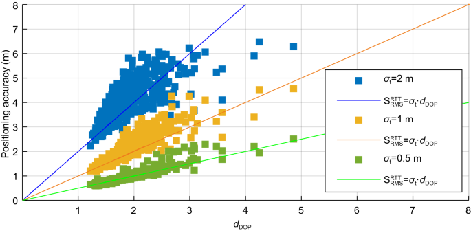
Relationship between positioning accuracy and observation accuracy in Multi-RTT positioning
The experimental results show that the 3D positioning accuracy is significantly correlated with the accuracy of observations, consistent with the theoretical formula, that is, the 3D positioning accuracy is equal to the \({d}_{\mathrm{DOP}}\) value times the accuracy of observations. In addition, because the \({d}_{\mathrm{DOP}}\) value is greater than 1, the positioning accuracy is lower than the observation accuracy.
The effects of different observation accuracies on 3D positioning accuracy after adding AOD are shown in Fig. 7 and Table 1 . When the accuracy of time delay measurements is kept the same, positioning accuracy after adding AOD is significantly improved. In addition, the correlation between the 3D position accuracy of RTT/AOD positioning and \({d}_{\mathrm{DOP}}\) becomes weak. This result indicates that the addition of AOD can lower the influence of poor \({d}_{\mathrm{DOP}}\) on positioning accuracy.
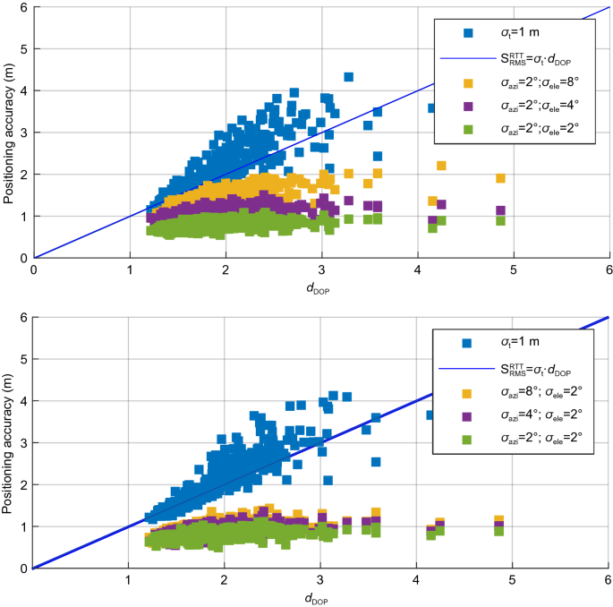
Relationship between positioning accuracy and observation accuracy in RTT/AOD positioning
Compared with Multi-RTT positioning, after adding AOD with an accuracy of 2°, the average 3D positioning accuracy enhances from 2.033 to 0.798 m, with an improvement of 60.7%. This result indicates that the integration of AOD greatly improves the positioning accuracy.
The influences of the azimuth and vertical angles on the positioning results are compared, and the following findings are obtained. When the accuracy of the azimuth angle is 2° and the accuracy of the vertical angle is 8° and 4°, respectively, the accuracy improvements are all below 50% compared with Multi-RTT positioning. When the accuracy of the vertical angle is 2°, and the accuracy of the azimuth angle is 8° and 4°, respectively, the accuracy improvements are all above 50% compared with Multi-RTT positioning. Accordingly, the influence of the accuracy of the azimuth angle on positioning accuracy is greater than that of the accuracy of the vertical angle.
Verify the influence of the number of base stations on positioning accuracy
This section involves simulation experiments with the proposed number of base stations changed to verify its influence on positioning accuracy. The experimental results are shown in Figs. 8 and 9 . The positioning accuracy with different numbers of base stations is shown in Fig. 8 , and the changes in the positioning accuracy after adding AOD are shown in Fig. 9 . As the proposed number of base stations increases, the average \({d}_{\mathrm{DOP}}\) gradually decreases. Similarly, as the number of base stations increases from 3 to 9, the accuracy enhances from 1.9 to 1.2 m in Multi-RTT positioning and from 1.1 to 0.7 m in RTT/AOD positioning. Overall, as the number of base stations increases, the positioning accuracy of Multi-RTT and RTT/AOD is improved. From the perspective of accuracy improvement, the effect of adding angle information is significantly better than increasing the number of base stations. The addition of angle information improves the positioning accuracy by approximately 50%, regardless of the number of base stations used for positioning.
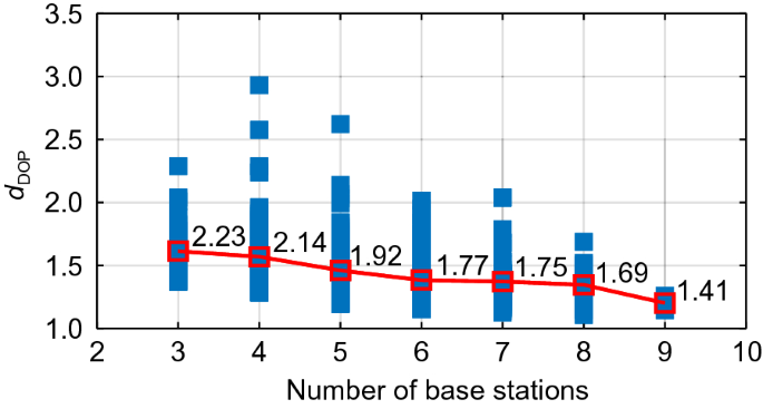
Relationship between \({d}_{\mathrm{DOP}}\) and the number of base stations
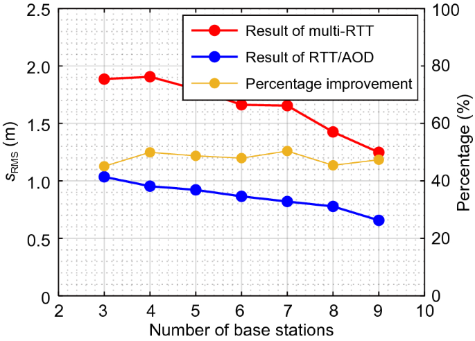
Variation of RMS with the number of base stations
Positioning performance in a complex environment
In complex scenes such as indoor and outdoor junctions and dense urban areas, the number of LOS signals will be reduced compared with that in the open environment due to the occlusion of buildings. In urban environments, we limited the number of base stations to 1–9 and also regarded the time as poor observation epoch when the number of base stations is not more than 3, otherwise good observation epoch. In the assumption of LOS propagation, the accuracy of observations is less affected by scene changes, so we believe that the accuracy of observations in complex scenes and good scenes are the same, i.e., RTT accuracy is 1 m, and AOD accuracy is 2°.
At least three base stations are required in Multi-RTT positioning, whereas RTT/AOD positioning needs only one base station. This section simulates a complex environment for further analysis. This environment often has less than three base stations during the positioning process. The number of base stations used for positioning at different epochs is shown in Fig. 10 . The proportion of epochs with base stations less than three is 27.7%.
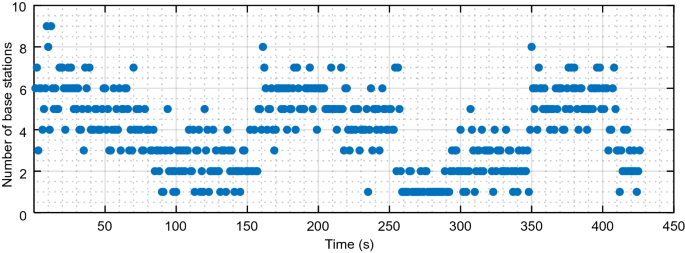
Number of observable base stations in a complex environment
The sequence of horizontal and vertical position errors in Multi-RTT and RTT/AOD positioning is presented in Fig. 11 . The statistical results, including the standard deviation of position error, the percentage of position error in each interval, and the percentage of epochs when the positioning converges are indicated in Fig. 12 and Table 2 . Given the limitation of the minimum number of base stations, the results in Multi-RTT positioning are relatively sparse, especially in second 150 to second 350, when the number of base stations is insufficient. By contrast, continuous and dense results are exhibited by RTT/AOD positioning, even with an insufficient number of base stations.
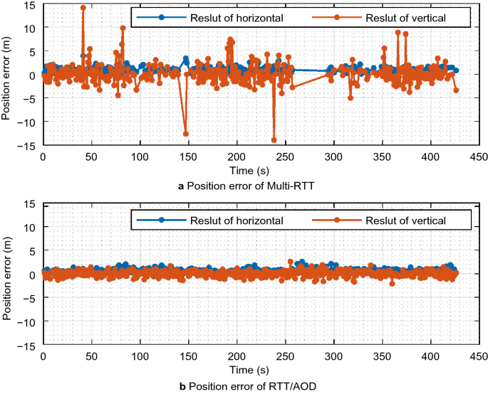
Position error in a complex environment
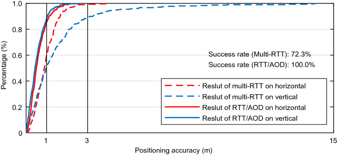
The Cumulative Distribution Function (CDF) of the accuracy of Multi-RTT and RTT/AOD positioning in a complex environment
In terms of positioning accuracy, after adding AOD, the horizontal and vertical accuracies are enhanced by approximately 27 and 65%, respectively. The reason for the greater enhancement in the vertical accuracy is that the vertical angle can provide redundant observations for vertical positioning, and its observation accuracy is better than that of the azimuth angle.
After adding AOD, the percentage of the epochs with a smaller position error has been greatly improved. In addition, the positioning reliability has been enhanced.
To sum up, the addition of AOD has the following advantages. It reduces the demand for the number of base stations, increases the proportion of the epochs for successful positioning, expands the scope of application of 5G positioning, and improves the accuracy and reliability of positioning in a complex environment.
Positioning performance in a good environment
This part will compare the changes in positioning accuracy before and after adding AOD when the observation condition is good. The number of base stations is around 3–7, and the proportion of the epochs with base stations less than three is only 2.8%, as shown in Fig. 13 .
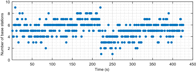
Number of observable base stations in a good environment
The positioning accuracy before and after adding AOD is compared in a good environment. The error sequence is presented in Fig. 14 , and the statistical results are listed in Fig. 15 and Table 3 . The position error sequences obtained by Multi-RTT and RTT/AOD positioning are continuous. However, in RTT/AOD, the frequency of large errors has been reduced. Finally, the horizontal and vertical accuracies are improved by approximately 39 and 76%.
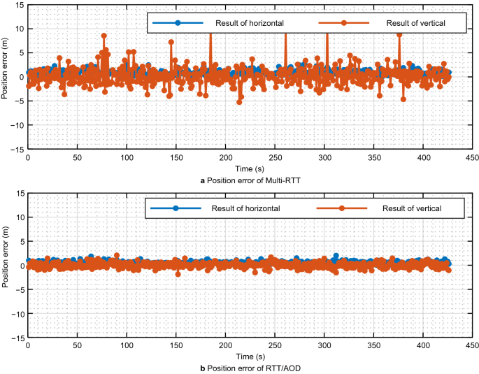
Position error in a good environment
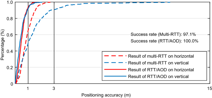
The CDF of the accuracy of Multi-RTT and RTT/AOD positioning in a good environment
In this study, we conducted the following investigation to improve the positioning performance of 5G with an insufficient number of observable base stations. First, the AOD capability of multi-antenna is integrated into 5G positioning, establishing a novel 5G positioning model with an intergartion of AOD and RTT. Then, the influences of the distribution of base stations and the accuracy of angle measurement on positioning accuracy are examed with theoretical analysis. The relationship between RTT/AOD positioning and base stations geometry distribution is deduced and analyzed theoretically. In a complex environment where the number of observable base stations and the distribution of base stations is not favorable, the addition of AOD measurements is tested to determine if the positioning accuracy and reliability can be imrpoved. Accordingly, simulation experiments are carried out in two scenarios with good and complex environments, respectively, to compare the difference before and after adding the AOD measurements. The experimental results show that the addition of the AOD measurements significantly improves the positioning accuracy. Specifically, the horizontal accuracy is improved by more than 25%, and the vertical by more than 65%. Adding the AOD measurements also affects the positioning reliability. The complete positioning capacity is realized, and the problem that the RTT measurements along cannot position in the scenario with less than three base stations is solved.
However, considerable work remains to be further studied to improve the performance of 5G positioning in a complex environment. Two aspects can be foreseen. One is to use the \({d}_{\mathrm{DOP}}\) value to select favorable base stations and determine if the AOD measurements are needed. The other is 5G positioning can be fused with inertial navigation for the application in the places with no observable 5G base station for a short period, such as in tunnelsand other occluded areas.
Availability of data and materials
The other data used in this study are available from the corresponding author upon request.
Chaloupka, Z. (2017). Technology and standardization gaps for high accuracy positioning in 5G. IEEE Communications Standards Magazine, 1 (1), 59–65.
Article Google Scholar
Cominelli, M., Patras, P., & Gringoli, F. (2019). Dead on arrival: An empirical study of the Bluetooth 5.1 positioning system. In: Proceedings of the 13th international workshop on wireless network testbeds, experimental evaluation & characterization. Los Cabos, Mexico, pp. 13–20.
del Peral-Rosado, J. A., López-Salcedo, J. A., Kim, S., & Seco-Granados, G. (2016). Feasibility study of 5G-based localization for assisted driving. In: Proceedings of the 2016 International conference on localization and GNSS (ICL-GNSS). Barcelona, Spain, pp. 1–6.
Dammann, A., Raulefs, R., & Zhang, S. (2015). On prospects of positioning in 5G. In: Proceedings of the 2015 IEEE International conference on communication workshop (ICCW). London, UK, pp. 1207–1213.
3GPP TS 38.305. (2020). NG Radio Access Network (NG-RAN); Stage 2 functional specification of User Equipment (UE) positioning in NG-RAN (Release 16).
3GPP TS 38.455. (2019). NG-RAN; NR Positioning Protocol A (NRPPa) (Release 15).
Groves, P. D. (2015). Principles of GNSS, inertial, and multisensor integrated navigation systems, 2nd edition [Book review]. IEEE Aerospace and Electronic Systems Magazine, 30 (2), 26–27.
Han, T. (2014). Research on GNSS multi-system satellite selection strategy. Ph.D. Thesis, Shanghai Jiaotong University, China.
Google Scholar
Keating, R., Säily, M., Hulkkonen, J., & Karjalainen, J. (2019). Overview of positioning in 5G new radio. In: Proceedings of the 2019 16th International symposium on wireless communication systems (ISWCS).Oulu, Finland, pp. 320–324.
Koivisto, M., Talvitie, J., Costa, M., Leppänen, K., & Valkama, M. (2018). Joint cmWave-based multiuser positioning and network synchronization in dense 5G networks. In: Proceedings of the 2018 IEEE Wireless Communications and Networking Conference (WCNC). Barcelona, Spain, pp. 1–6.
Koivisto, M., Costa, M., Werner, J., Heiska, K., Talvitie, J., Leppänen, K., & Valkama, M. (2017a). Joint device positioning and clock synchronization in 5G ultra-dense networks. IEEE Transactions on Wireless Communications, 16 (5), 2866–2881.
Koivisto, M., Hakkarainen, A., Costa, M., Kela, P., Leppanen, K., & Valkama, M. (2017b). High-efficiency device positioning and location-aware communications in dense 5G networks. IEEE Communications Magazine, 55 (8), 188–195.
Li, Y. Y., Qi, G. Q., & Sheng, A. D. (2018). Performance metric on the best achievable accuracy for hybrid TOA/AOA target localization. IEEE Communications Letters, 22 (7), 1474–1477.
Liu, Y., Shi, X., He, S., & Shi, Z. (2017). Prospective positioning architecture and technologies in 5G networks. IEEE Network, 31 (6), 115–121.
Monfared, S., Nguyen, T. H., Petrillo, L., De Doncker, P., & Horlin, F. Experimental demonstration of BLE transmitter positioning based on AOA estimation. In: Proceedings of the 2018 IEEE 29th Annual international symposium on personal, Indoor and mobile radio communications (PIMRC). Bologna, Italy, pp. 856–859.
Shahmansoori, A., Garcia, G. E., Destino, G., Seco-Granados, G., & Wymeersch, H. (2017). Position and orientation estimation through millimeter-wave MIMO in 5G systems. IEEE Transactions on Wireless Communications, 17 (3), 1822–1835.
Su, W., & Deng, Z. (2020). Research on the weight distribution of helmert variance component estimation in Beidou+ 5G Integrated positioning. In: Sun J, Yang C, Xie J. (eds) China Satellite Navigation Conference (CSNC) 2020 Proceedings: Volume III. CSNC 2020. Lecture Notes in Electrical Engineering, vol 652. Springer, Singapore. https://doi.org/10.1007/978-981-15-3715-8_39 .
Sun, C., Zhao, H., Bai, L., Cheong, J. W., Dempster, A. G., & Feng, W. (2020). GNSS-5G hybrid positioning based on TOA/AOA measurements. In: Sun J, Yang C, Xie J. (eds) China Satellite Navigation Conference (CSNC) 2020 Proceedings: Volume III. CSNC 2020. Lecture Notes in Electrical Engineering, vol 652. Springer, Singapore. https://doi.org/10.1007/978-981-15-3715-8_47 .
Torrieri, D. J. (1984). Statistical theory of passive location systems. IEEE Transactions on Aerospace and Electronic Systems, 2 , 183–198.
Wang, Y., & Ho, K. C. (2015). An asymptotically efficient estimator in closed-form for 3-D AOA localization using a sensor network. IEEE Transactions on Wireless Communications, 14 (12), 6524–6535.
Wen, F., Wymeersch, H., Peng, B., Tay, W. P., So, H. C., & Yang, D. (2019). A survey on 5G massive MIMO localization. Digital Signal Processing, 94 , 21–28.
Wymeersch, H., Seco-Granados, G., Destino, G., Dardari, D., & Tufvesson, F. (2017). 5G mmWave positioning for vehicular networks. IEEE Wireless Communications, 24 (6), 80–86.
Download references
Acknowledgements
Not applicable.
This work was supported by the National Key Research and Development Program of China under Grant No. 2018YFC0809804, the National Science Foundation of China under Grant No. 41974038, and the major consulting research project of the Chinese Academy of Engineering(HB2020B13).
Author information
Authors and affiliations.
Wuhan University, Wuhan, Hubei, China
Wenfei Guo, Yue Deng, Chi Guo, Shufeng Qi & Jingrong Wang
You can also search for this author in PubMed Google Scholar
Contributions
WFG put forward the main ideas and ideas of the article, and YD completed the experiment, writing and analysis part of the article. All the authors read and approved the manuscript.
Authors information
Wenfei Guo is an associate professor at GNSS Research Center, Wuhan University. He received his PhD in Communication and Information Systems from Wuhan University in 2011. His research focuses on GNSS receivers and relevant signal processing technologies, including high precise timing receivers, GNSS-R receivers and anti-jamming receivers, etc.
Yue Deng received the B.S. degree in navigation engineering at the School of Geodesy and Geomatics, Wuhan University, in 2018. She is currently pursuing the M.S. degree in Navigation, Guidance and Control at the School of Geodesy and Geomatics, Wuhan University, China. Her area of interests includes indoor and outdoor positioning.
Chi Guo received the MEng and PhD degrees in computer science from Wuhan University, Hubei province, China. Currently, he is an associate professor at the national satellite positioning system engineering technology research center of Wuhan University. His current research interests include Beidou application, unmanned system navigation and location based services (LBS).
Shufeng Qi received the B.S. degree in Faculty of Geosciences and Environmental Engineering, Southwest Jiaotong University, in 2020. He is currently pursuing the M.S. degree in GNSS Research Center, Wuhan University, China. His area of interests includes 5G positioning and 5G/GNSS.
Jingrong Wang received the M.S. degree in surveying and mapping engineering from the State Key Laboratory of Information Engineering in Surveying, Mapping and Remote Sensing, Wuhan University in 2018. He is currently pursuing the PhD degree in Geodesy and Surveying Engineering at GNSS Research Center of Wuhan University. His current interests include indoor and outdoor positioning, and research on channel estimation algorithms in 5G systems.
Corresponding author
Correspondence to Chi Guo .
Ethics declarations
Competing interests.
The authors declare that they have no competing interests.
Additional information
Publisher's note.
Springer Nature remains neutral with regard to jurisdictional claims in published maps and institutional affiliations'' (in PDF at the end of the article below the references; in XML as a back matter article note).
If the transition matrix and weight matrix of Multi-RTT positioning are \({{\varvec{H}}}_{t}\) and \({\varvec{P}}\) , respectively, after adding an angle observation of precision \({\sigma }_{\alpha }\) , the transition matrix and the weight matrix become \({{\varvec{H}}}_{t}^{^{\prime}}\) and \({{\varvec{P}}}^{^{\prime}}\) .
In the matrix \({{\varvec{H}}}_{t}^{^{\prime}}\) , the row vector corresponding to the angle observations is \({\varvec{h}}\) . Then,
given that the weight matrices \({{\varvec{P}}}_{t}\) and \({{\varvec{P}}}^{^{\prime}}\) are the reciprocal of the observed error variance, and each observation is independent, \({{\varvec{P}}}_{t}\) can be decompressed into the product of two diagonal matrices as follows:
Singular value decomposition is performed for \({{\varvec{H}}}_{t}{{\varvec{R}}}_{t}\)
where \({\varvec{U}}\) and \({\varvec{V}}\) are orthogonal matrices, and \({\varvec{S}}\) is a diagonal matrix. By substituting ( 22 ) and ( 23 ) into ( 21 ) and making an orthogonal transformation, the following equations can be obtained:
Orthogonal transformation does not affect the trace of the matrix. Thus,
where \(k=\sum_{i=1}^{3}{\left(\frac{{v}_{j}}{{z}_{jj}}\right)}^{2}>0\) , \(f=\sum_{i=1}^{3}\frac{{{v}_{j}}^{2}}{{z}_{jj}}>0\) . Accordingly,
When m azimuth angles and n vertical angles exist, then
where corner marks \(\alpha\) and \(\beta\) denote azimuth angle and vertical angle, respectively. In ( 29 ), given that \({\sigma }_{\alpha }^{2}\) , \(k\) , and \(f\) are all positive real numbers, \({({s}_{\mathrm{RMS}}^{\mathrm{RTT}/\mathrm{AOD}})}^{2}<{({s}_{\mathrm{RMS}}^{\mathrm{RTT}})}^{2}\) .
Rights and permissions
Open Access This article is licensed under a Creative Commons Attribution 4.0 International License, which permits use, sharing, adaptation, distribution and reproduction in any medium or format, as long as you give appropriate credit to the original author(s) and the source, provide a link to the Creative Commons licence, and indicate if changes were made. The images or other third party material in this article are included in the article's Creative Commons licence, unless indicated otherwise in a credit line to the material. If material is not included in the article's Creative Commons licence and your intended use is not permitted by statutory regulation or exceeds the permitted use, you will need to obtain permission directly from the copyright holder. To view a copy of this licence, visit http://creativecommons.org/licenses/by/4.0/ .
Reprints and permissions
About this article
Cite this article.
Guo, W., Deng, Y., Guo, C. et al. Performance improvement of 5G positioning utilizing multi-antenna angle measurements. Satell Navig 3 , 17 (2022). https://doi.org/10.1186/s43020-022-00078-y
Download citation
Received : 10 November 2021
Accepted : 26 June 2022
Published : 05 September 2022
DOI : https://doi.org/10.1186/s43020-022-00078-y
Share this article
Anyone you share the following link with will be able to read this content:
Sorry, a shareable link is not currently available for this article.
Provided by the Springer Nature SharedIt content-sharing initiative
- 5G positioning
- Angle of departure
- Positioning accuracy
- Positioning reliability

timing advance in 5g
Here's a more detailed explanation of how Timing Advance works in the context of 5G:
- Round-Trip Time (RTT): The timing advance process relies on measuring the Round-Trip Time (RTT) of the signal between the mobile device and the base station. RTT is the time taken for a signal to travel from the transmitter (UE) to the receiver (gNB) and back.
- The mobile device transmits a signal to the base station.
- The base station receives the signal and measures the time it took for the signal to travel from the UE to the gNB.
- The base station calculates the Timing Advance based on the measured RTT.
- The TA is essentially the time it takes for the signal to travel from the UE to the gNB divided by two (since it's a round-trip measurement) and converted into a delay in the time domain.
- The calculated TA is then communicated to the UE.
- The UE adjusts its transmission timing by delaying its transmissions by the amount specified by the TA.
- By adjusting the transmission timing, the signals from different UEs are synchronized at the base station.
- This synchronization is crucial for the base station to effectively separate and decode signals from multiple UEs.
- The timing advance is not a static value; it can change dynamically based on factors such as UE mobility and changes in radio conditions.
- The base station may periodically update the TA to account for these changes.
Timing Advance in 5G is a mechanism for synchronizing the transmission timing between the UE and the gNB. It is based on the measurement of Round-Trip Time and involves the calculation and adjustment of the transmission timing to ensure efficient and interference-free communication in the wireless network.

Written by Vasilena Markova • September 27, 2023 • 12:58 pm • Internet

Round-Trip Time (RTT): What It Is and Why It Matters
Round-Trip Time (RTT) is a fundamental metric in the context of network performance, measuring the time it takes for data packets to complete a round trip from source to destination and back. Often expressed in milliseconds (ms), RTT serves as a critical indicator for evaluating the efficiency and reliability of network connections. In today’s article, we dive into the concept of RTT, exploring how it works, why it matters in our digital lives, the factors that influence it, and strategies to enhance it. Whether you’re a casual internet user seeking a smoother online experience or a network administrator aiming to optimize your digital infrastructure, understanding this metric is critical in today’s interconnected world.
Table of Contents
What is Round-Trip Time (RTT)?
Round-Trip Time is a network performance metric representing the time it takes for a data packet to travel from the source to the destination and back to the source. It is often measured in milliseconds (ms) and is a crucial parameter for determining the quality and efficiency of network connections.
To understand the concept of RTT, imagine sending a letter to a friend through the postal service. The time it takes for the letter to reach your friend and for your friend to send a reply back to you forms the Round-Trip Time for your communication. Similarly, in computer networks, data packets are like those letters, and RTT represents the time it takes for them to complete a round trip.
How Does it Work?
The concept of RTT can be best understood by considering the journey of data packets across a network. When you request information from a web server, for example, your device sends out a data packet holding your request. This packet travels through various network devices in between, such as routers and switches, before reaching the destination server. Once the server processes your request and prepares a response, it sends a data packet back to your device.
Round-Trip Time is determined by the time it takes for this data packet to travel from your device to the server (the outbound trip) and then back from the server to your device (the inbound trip). The total RTT is the sum of these two one-way trips.
Let’s break down the journey of a data packet into several steps so you can better understand the RTT:
- Sending the Packet: You initiate an action on your device that requires data transmission. For example, this could be sending an email, loading a webpage, or making a video call.
- Packet Travel: The data packet travels from your device to a server, typically passing through multiple network nodes and routers along the way. These middle points play a significant role in determining the RTT.
- Processing Time: The server receives the packet, processes the request, and sends a response back to your device. This processing time at both ends also contributes to the Round-Trip Time.
- Return Journey: The response packet makes its way back to your device through the same network infrastructure, facing potential delays on the route.
- Calculation: It is calculated by adding up the time taken for the packet to travel from your device to the server (the outbound trip) and the time it takes for the response to return (the inbound trip).
Why does it matter?
At first look, Round-Trip Time (RTT) might seem like technical terminology, but its importance extends to various aspects of our digital lives. It matters for many reasons, which include the following:
- User Experience
For everyday internet users, RTT influences the sensed speed and responsiveness of online activities. Low Round-Trip Time values lead to a seamless experience, while high RTT can result in frustrating delays and lag during tasks like video streaming, online gaming, or live chats.
- Network Efficiency
Network administrators and service providers closely monitor RTT to assess network performance and troubleshoot issues. By identifying bottlenecks and areas with high RTT, they can optimize their infrastructure for better efficiency.
- Real-Time Applications
Applications that rely on real-time data transmission, such as VoIP calls, video conferencing, and online gaming, are highly sensitive to RTT. Low RTT is crucial for smooth, interruption-free interactions.
In cybersecurity, Round-Trip Time plays a role in detecting network anomalies and potential threats. Unusually high RTT values can be a sign of malicious activity or network congestion.
Factors Affecting Round-Trip Time (RTT)
Several factors can influence the metric, both positively and negatively. Therefore, understanding these factors is crucial, and it could be very beneficial for optimizing network performance:
- Distance: The physical distance between the source and destination plays a significant role. Longer distances result in higher RTT due to the time it takes for data to travel the network.
- Network Congestion: When a network experiences high volumes of traffic or congestion, data packets may be delayed as they wait for their turn to be processed. As a result, it can lead to packet delays and increased RTT.
- Routing: The path a packet takes through the network can significantly affect RTT. Efficient routing algorithms can reduce the time, while not-so-optimal routing choices can increase it.
- Packet Loss: Packet loss during transmission can occur due to various reasons, such as network errors or congestion. When lost, packets need to be retransmitted, which can seriously affect the Round-Trip Time.
- Transmission Medium: It is a critical factor influencing RTT, and its characteristics can vary widely based on the specific medium being used. Fiber optic cables generally offer low RTT due to the speed of light in the medium and low signal loss. In contrast, wireless mediums can introduce variable delays depending on environmental factors and network conditions.
How to improve it?
Improving Round-Trip Time (RTT) is a critical goal for network administrators and service providers looking to enhance user experiences and optimize their digital operations. While some factors affecting it are beyond our control, there are strategies and practices to optimize Round-Trip Time for a smoother online experience:
- Optimize Routing: Network administrators can optimize routing to reduce the number of hops data packets take to reach their destination. This can be achieved through efficient routing protocols and load balancing .
- Optimize Network Infrastructure: For businesses, investing in efficient network infrastructure, including high-performance routers and switches, can reduce internal network delays and improve RTT.
- Upgrade Hardware and Software: Keeping networking equipment and software up-to-date ensures that you benefit from the latest technologies and optimizations that can decrease RTT.
- Implement Caching: Caching frequently requested data closer to end-users can dramatically reduce the need for data to travel long distances. The result really helps with lowering RTT.
- Monitor and Troubleshoot: Regularly monitor your network for signs of congestion or packet loss. If issues arise, take steps to troubleshoot and resolve them promptly.
Discover ClouDNS Monitoring service!
Round-Trip Time (RTT) is the silent force that shapes our online experiences. From the seamless loading of web pages to the quality of our video calls, RTT plays a pivotal role in ensuring that digital interactions happen at the speed of thought. As we continue to rely on the Internet for work, entertainment, and communication, understanding and optimizing this metric will be crucial for both end-users and network administrators. By reducing it through strategies, we can have a faster, more responsive digital world where our online activities are limited only by our imagination, not by lag.
Hello! My name is Vasilena Markova. I am a Marketing Specialist at ClouDNS. I have a Bachelor’s Degree in Business Economics and am studying for my Master’s Degree in Cybersecurity Management. As a digital marketing enthusiast, I enjoy writing and expressing my interests. I am passionate about sharing knowledge, tips, and tricks to help others build a secure online presence. My absolute favorite thing to do is to travel and explore different cultures!

Related Posts

Ping Traffic Monitoring: Ensuring Network Health and Efficiency
March 28, 2024 • Monitoring
In an era where digital connectivity is the lifeline of businesses and individuals alike, maintaining optimal network performance is more ...
Leave a Reply Cancel reply
Your email address will not be published. Required fields are marked *
Recent Posts
- Network Monitoring: Ensuring the Pulse of Digital Communications
- rDNS explained in detail
- What is Authoritative DNS server?
- IPv4 vs IPv6 and where did IPv5 go?
- What is a Secondary DNS server?
- Cloud Computing
- DNS Records
- Domain names
- Load balancing
- SSL Certificates
- Web forwarding
- DNS Services
- Managed DNS
- Dynamic DNS
- Secondary DNS
- Reverse DNS
- DNS Failover
- Anycast DNS
- Email Forwarding
- Enterprise DNS
- Domain Names
Enhancement of Performance of Round-Trip Time Using Kalman Filtering
- Conference paper
- First Online: 11 April 2021
- Cite this conference paper

- N. G. Goudru ORCID: orcid.org/0000-0003-0712-3591 37 ,
- R. P. Puneeth 38 &
- Krishna Prasad N. Rao 38
Part of the book series: Lecture Notes in Electrical Engineering ((LNEE,volume 752))
583 Accesses
Round-trip time (RTT) is an important component for smooth end-to-end congestion control, seamless data flow and for bandwidth estimation in Internet. In transport layer, the performance of a TCP flow directly depends on its RTT value. RTT is the time elapsed for the instant a packet is released by the sender to the instant the corresponding acknowledgement is received by the sender. The study of RTT distribution throws light in understanding the data rate realized by an individual TCP flow in a shared link, queue length along the bottleneck link of a router and the dynamics of sender window. In this paper, a stochastic model defining RTT estimation is considered. The performance of the model is enhanced by applying one-dimensional Kalman filter. Kalman filter is used to eliminate the noise introduced into the signals during transmission of data from source to destination. The combination of the aggregated model with a bias term gives more accurate RTT value. The bias term in the model define Kalman filtering applied for noise elimination. The RTT values calculated using model is regarded as RTT estimation values, and RTT values captured using Wireshark tool are regarded as RTT measurement values. The enhancement of performance of RTT estimation model is demonstrated by inferring statistical data and graphs obtained using MATLAB programming.
This is a preview of subscription content, log in via an institution to check access.
Access this chapter
- Available as PDF
- Read on any device
- Instant download
- Own it forever
- Available as EPUB and PDF
- Compact, lightweight edition
- Dispatched in 3 to 5 business days
- Free shipping worldwide - see info
- Durable hardcover edition
Tax calculation will be finalised at checkout
Purchases are for personal use only
Institutional subscriptions
N. Cardwell, S. Savage, T. Anderson, Modeling Latency TCP (Department of Computer science and Engineering, University of Washington, Seattle, WA 98195, USA, 2000)
Google Scholar
K. Jacobsson, H. Hjalmarsson, N. Moller, K. Henrik Johansson, Estimation of RTT and Bandwidth for Congestion Control Applications in Communication Networks (Department of Signals, Sensors and Systems, KTH, SE-100 44 Stockholm, Sweden, 2005)
S. Shakkottai, R. Srikant, The RTT Distribution of TCP Flows in the Internet and Its Impact on TCP-Based Flow Control (University of Illinois, Illinois, USA, 2005).
Z. Zhu, A.M.K Cheng, Worst Case Round Trip Time Prediction and Statistical Analysis Using Extreme Values Theory (Real-time system laboratory, Department of Computer Science, University of Houston, Texas, 77204, USA, 2005)
K. Jacobsson, H. Hjalmarsson, N. Moller, Karl Henrik Johansson, Round-Trip Time Estimation in Communication Networks Using Adaptive Kalman Filtering (Department of Signals, Sensors and Systems, KTH, SE-100 44 Stockholm, Sweden, 2005)
G. Carlucci, L. De Cicco, S. Holmer, S. Mascolo, Congestion Control for Web Real-Time Communication (IEEE/ACM Trans, Netw, 2017).
Book Google Scholar
Q. Su, J. Gong, X. Hu, RTT estimation with sampled flow data. IEICE Trans. Commun. E98–B (9) (2015)
B.A.A. Nunes, K. Veenstra, W. Ballenthin, S. Lukin, K. Obraczka, A Machine learning approach to end-to-end RTT estimation and its application to TCP. 978–1–4577–0638–7 /11/$26.00 ©2011 IEEE
I. Prieto, M. Izal, E. Magaña, D. Morato, A simple passive method to estimate RTT in high bandwidth-delay networks, in The Seventh International Conference on Evolving Internet (Public University of Navarre, Navarre, Spain, 2015)
H. Jiang, C. Dovrolis, Passive Estimation of TCP Round-Trip Times (University of Delaware, Computer and Information Sciences, 2011).
Z. Zhao, S. Darbha, A.L. Narasimha Reddy, A method for estimating the proportion of nonresponsive traffic at a router. IEEE/ACM Trans. Netw. 12 (4) (2004)
C.V. Hollot, Y. Liu, V. Misra, D. Towsley, Unresponsive flows and AQM performance. IEEE INFOCOM (2003)
N. G. Goudru, B.P. Vijayakumar, Evaluation of TCP performance using NDG loss predictor in wireless networks. https://doi.org/10.1109/ADCOM.2015.10
Download references
Author information
Authors and affiliations.
Department of Information Science and Engineering, Nitte Meenakshi Institute of Technology (affiliated to Visvesvaraya Technological University), Bengaluru, India
N. G. Goudru
Department of Computer Science and Engineering, NMAM Institute of Technology (affiliated to Visvesvaraya Technological University), Nitte, Udupi, India
R. P. Puneeth & Krishna Prasad N. Rao
You can also search for this author in PubMed Google Scholar
Corresponding author
Correspondence to N. G. Goudru .
Editor information
Editors and affiliations.
Engineering Product Development, Singapore University of Technology and Design, Singapore, Singapore
Shubhakar Kalya
Department of Electronics and Communication Engineering, National Institute of Technology Karnataka, Surathkal, Karnataka, India
Muralidhar Kulkarni
Department of Electronics and Communication Engineering, N.M.A.M. Institute of Technology, Nitte, Udupi, Karnataka, India
K. S. Shivaprakasha
Rights and permissions
Reprints and permissions
Copyright information
© 2021 The Author(s), under exclusive license to Springer Nature Singapore Pte Ltd.
About this paper
Cite this paper.
Goudru, N.G., Puneeth, R.P., Rao, K.P.N. (2021). Enhancement of Performance of Round-Trip Time Using Kalman Filtering. In: Kalya, S., Kulkarni, M., Shivaprakasha, K.S. (eds) Advances in VLSI, Signal Processing, Power Electronics, IoT, Communication and Embedded Systems. Lecture Notes in Electrical Engineering, vol 752. Springer, Singapore. https://doi.org/10.1007/978-981-16-0443-0_8
Download citation
DOI : https://doi.org/10.1007/978-981-16-0443-0_8
Published : 11 April 2021
Publisher Name : Springer, Singapore
Print ISBN : 978-981-16-0442-3
Online ISBN : 978-981-16-0443-0
eBook Packages : Engineering Engineering (R0)
Share this paper
Anyone you share the following link with will be able to read this content:
Sorry, a shareable link is not currently available for this article.
Provided by the Springer Nature SharedIt content-sharing initiative
- Publish with us
Policies and ethics
- Find a journal
- Track your research
Round Trip Time Estimation Based on Adaptive Filtering
Ieee account.
- Change Username/Password
- Update Address
Purchase Details
- Payment Options
- Order History
- View Purchased Documents
Profile Information
- Communications Preferences
- Profession and Education
- Technical Interests
- US & Canada: +1 800 678 4333
- Worldwide: +1 732 981 0060
- Contact & Support
- About IEEE Xplore
- Accessibility
- Terms of Use
- Nondiscrimination Policy
- Privacy & Opting Out of Cookies
A not-for-profit organization, IEEE is the world's largest technical professional organization dedicated to advancing technology for the benefit of humanity. © Copyright 2024 IEEE - All rights reserved. Use of this web site signifies your agreement to the terms and conditions.
Round-Trip Time (RTT)
Last Edited
In the intricate domain of computer networking, Round-Trip Time, popularly known as RTT, plays an instrumental role. RTT signifies the time it takes for a data packet to travel from a source to a destination and back again. It serves as a key performance metric in networking, helping diagnose network speed and efficiency.
What is RTT?
To understand what RTT is, envision playing catch with a ball. You throw the ball (this represents the data packet), and your friend catches it (this is the packet reaching its destination). Then, your friend throws the ball back to you (the packet’s return journey). The total time from the initial throw to catching the ball again is akin to RTT in networking.
RTT is not about how quickly the ball is thrown or caught; rather, it’s about the total duration of the journey. Similarly, in the digital world, RTT measures the full journey of a data packet, irrespective of the data size or transmission speed.
The Importance of Round-Trip Time
RTT is pivotal for network administrators because it helps to measure network latency or delay. It’s a vital metric used to determine the performance of network connections, allowing administrators to identify potential issues and gauge the quality of the network.
A lower Round-Trip Time indicates a faster connection, resulting in improved data transfer and a superior user experience. Conversely, a high RTT may suggest network congestion, poor routing, or other issues leading to increased latency.
How to Measure RTT?
A common method to measure RTT is by using the ‘ping’ command . This command sends an Internet Control Message Protocol (ICMP) request to a specified server, which then sends an ICMP reply back. The time it takes for this round-trip journey is the RTT, typically measured in milliseconds (ms).
Another method involves using Traceroute, a command-line tool that displays the path that a packet takes to reach its destination, recording the latency at each hop.
RTT and Its Impact on Applications
RTT is particularly critical for real-time applications such as video conferencing, VoIP calls, online gaming, and live streaming. High Round-Trip Time values in these applications can lead to noticeable delays, buffering, and synchronization issues, disrupting the user experience.
In non-real-time applications, like email or file transfer, high RTT might not be immediately noticeable to the user but could slow down overall data transfer rates.
Understanding RTT is a fundamental aspect of grasping how networks operate. It allows us to measure and diagnose network performance, directly impacting how we experience the internet and online services. By paying attention to RTT, network administrators can ensure optimal network performance, paving the way for efficient, seamless digital communication.
- RFC 7982 – Measurement of Round-Trip Time and Fractional Loss Using Session Traversal Utilities for NAT (STUN)

IMAGES
VIDEO
COMMENTS
Release-16 Single-cell and Multi-cell positioning Round-trip time (RTT) and angle of arrival (AoA) positioning techniques combined for single-digit meter-level precision Showcasing the benefits of ML and sensor fusion. 26 AI/ML for enhanced 5G positioning performance 5G positioning measurements (e.g., RTT + AoA)
•Multi-Cell Round-Trip-Time (MC-RTT) •TDD-level accuracy recommended (3 µs) •Enhanced Cell Identity (eCID) •TDD-level accuracy recommended (3 µs) 7 Measurement Methods. 8 Pseudo-Range Based Methods Time Difference of Arrival (DL-TDOA) Relative Time of Arrival (UL-RTOA) TP 2 RP 2 TP 1
Multi-cell round trip time (RTT): The gNB and UE perform Rx-Tx time difference measurement for the signal of each cell. The measurement reports from the UE and gNBs are sent to the location server to determine the round trip time of each cell and derive the UE position. Enhanced cell ID (E-CID).
Rel-16 introduced time-based positioning methods for NR standalone deployments (multi-round-trip time (RTT), Downlink and Uplink Time Difference of Arrival), as well as an angle-of-arrival and angle-of-departure-based positioning measurements, which can be used in combination with timing-based solutions to achieve higher accuracy.
Round-trip time (RTT) with one or more neighbouring base station (multi-RTT) In addition, Enhanced Cell-ID (E-CID) based on radio resource management (RRM) measurements is supported in 5G NR Rel-16. ... 3.3.5 Multi-Round-Trip-Time (Multi-RTT) Positioning. DL-TDOA and UL-TDOA positioning methods are based on time-of-arrival (TOA) measurements ...
• Multi-cell round-trip-time (Multi-RTT): gNB and UE perform Rx-Tx time difference measurement, using PRS and SRS signaling, for the signal of each cell. LMF initiates the procedure whereby multiple gNBs and a UE perform the gNB Rx-Tx and UE Rx-Tx measurements, respectively. Multi-RTT has higher accuracy than TDOA-based methods and relaxes ...
Since 4G LTE, mobile networks have supported observed time difference of arrival (OTDOA), uplink time difference of arrival (UL-TDOA) and positioning methods based on power measurements. In 5G, the list of supported methods is extended to include round trip time (RTT) and angle-based positioning.
The aim of this study is to improve the performance of the 5G positioning in complex environments with an insufficient number of observable base stations. First, the Angle of Departure (AOD) capability of multi-antennas is integrated into Multi-Round-Trip-Time (Multi-RTT) positioning, establishing a novel 5G RTT/AOD positioning model.
First, the Angle of Departure (AOD) capability of multi-antennas is integrated into Multi-Round-Trip-Time (Multi-RTT) positioning, establishing a novel 5G RTT/AOD positioning model. Then, the influencing factors of positioning performance, including the Dilution of Precision (DOP) and the accuracy of the AOD measurements, is analyzed.
Abstract—We consider a single-anchor multiple-input multiple-output orthogonal frequency-division multiplexing system with imperfectly synchronized transmitter (Tx) and ... (AOD), uplink (UL)-angle of arrival (AOA) and multi-cell round-trip time (RTT) [4], in addition to the already existing ones in previous generations of cellular networks ...
Multi-RTT multi-cell round trip time NAS Non-access stratum NG-C next- generation core network ng-eNB Next generation eNodeB NG-RAN New Generation Radio Access Network NGAP NG application protocol NLOS none-line of sight NR New Radio NRPPa new radio positioning protocol A OTDOA observed time difference of arrival ...
TDOA, multi round-trip-time (RTT), DL AOA, UL AOA, and E-CID. In 5G Release 18, 3GPP continues NR positioning evolution by studying solutions for side-link positioning, extending positioning support for reduced capability UEs, and further improving positioning accuracy. From Release 17, 3GPP has started standardizing enhanced mobile broadband ...
Round-trip time (RTT) is a key indicator of network performance, user Quality of Experience (QoE), and routing-protocol attacks [17, 31]. RTT relates directly to Transmission Control Protocol (TCP) throughput and also heavily influences higher-level metrics such as video QoE and page load time [6, 10]. Changes in RTTs can also be symptoms of ...
Round-Trip Time (RTT): The timing advance process relies on measuring the Round-Trip Time (RTT) of the signal between the mobile device and the base station. RTT is the time taken for a signal to travel from the transmitter (UE) to the receiver (gNB) and back. Transmission Timing: The mobile device transmits a signal to the base station.
The paper presents the details of a round trip time (RTT) positioning algorithm that provides a largely improved accuracy as compared to cell ID positioning - yet with an availability above 95% and a typical response time below 0.3 s. The paper presents the details of a round trip time (RTT) positioning algorithm that provides a largely improved accuracy as compared to cell ID positioning ...
The paper presents the details of a round trip time (RTT) positioning algorithm that provides a largely improved accuracy as compared to cell ID positioning - yet with an availability above 95% and a typical response time below 0.3 s. The algorithm fuses an RTT measurement with configured or computed cell polygon data, in order to determine an arc with left and right angles, and with the ...
Round-Trip Time is a network performance metric representing the time it takes for a data packet to travel from the source to the destination and back to the source. It is often measured in milliseconds (ms) and is a crucial parameter for determining the quality and efficiency of network connections. To understand the concept of RTT, imagine ...
Round-trip time (RTT) is an important component for smooth end-to-end congestion control, seamless data flow and for bandwidth estimation in Internet. In transport layer, the performance of a TCP flow directly depends on its RTT value. RTT is the time elapsed for the instant a packet is released by the sender to the instant the corresponding ...
IEEE 802.11-2016 has standardized the fine timing measurement (FTM) protocol that allows a station to accurately measure the round trip time (RTT) between it and another station. Fig. 1 shows a single burst of the FTM process with three FTM interchanges per burst. The protocol starts with an FTM Request packet sent from the initiating station ...
TCP Round-Trip Time by matching data packets with their associated acknowledgments. This enables monitoring of the RTT of all outgoing traffic in real time without installing software on the end hosts.To satisfy the stringent memory size and access constraints of programmable switches, our algorithm uses a multi-stage hash table to efficiently ...
To improve the performance of TCP transmission, round-trip time (RTT) estimation is often adopted as an effective approach. There exist many positive or passive methods for RTT estimation, but rarely of them take account of RTT's self-similarity which should not be ignored. In this paper, a new RTT estimation algorithm employing adaptive filtering is proposed. The algorithm is based on RTT's ...
ABSTRACT. Round-trip time (RTT) is a central metric that influences end-user QoE and can expose traffic-interception attacks. Many popular RTT monitoring techniques either send active probes (that do not capture application-level RTTs) or passively monitor only the TCP handshake (which can be inaccurate, especially for long-lived flows).
Round-Trip Time (RTT) In the intricate domain of computer networking, Round-Trip Time, popularly known as RTT, plays an instrumental role. RTT signifies the time it takes for a data packet to travel from a source to a destination and back again. It serves as a key performance metric in networking, helping diagnose network speed and efficiency.
Request/Response protocols and round-trip time (RTT) Redis is a TCP server using the client-server model and what is called a Request/Response protocol. This means that usually a request is accomplished with the following steps: The client sends a query to the server, and reads from the socket, usually in a blocking way, for the server response.