- Switch skin
Home > Protection > Tripping Curves of Circuit Breakers – B, C, D, K and Z Trip Curve

Tripping Curves of Circuit Breakers – B, C, D, K and Z Trip Curve
Types of circuit breaker based on its tripping curve.
A circuit breaker is a protection device employed in every electrical circuit to prevent any potential hazard. There are different types of circuit breakers used all over the world due to their various characteristics & applications. It is necessary to have a circuit breaker that offers adequate protection so that one can work safely around it without having fear of any potential hazards. That is why it is best to know about these kinds of circuit breakers & what kinds of protection do they offer before buying one.
Table of Contents
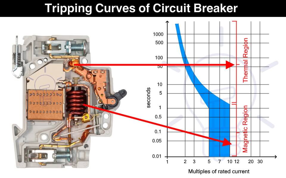
What is a Circuit Breaker?
A circuit breaker is an electrical device that provides protection against fault current. It breaks the circuit in case of overloading & short circuit. The fault currents generated due to these fault conditions can damage the electrical devices as well as cause fire in a building that can also pose danger to human life.
The circuit breaker instantly cut off the power supply to reduce further damage. A circuit breaker has two types of tripping unit i.e. thermal and magnetic tripping unit.
Thermal Tripping Unit: the thermal tripping unit is used for protection against overloading. It uses a bi-metallic contact that bends with a change in temperature. The current flowing through the bimetallic strip heats up contact & trip the circuit breaker.
The rate of bending of the bi-metallic strip depends on the amount of current. Therefore, greater the overloading current, faster the circuit breaker trips.
Magnetic Tripping Unit: The magnetic trip unit is used for protection against short circuit current. it includes a solenoid that produced a strong magnetic field due to high short circuit current to instantly trip the circuit breaker.
Related Posts:
- MCB (Miniature Circuit Breaker) – Construction, Working, Types & Applications
- MCCB (Molded Case Circuit Breaker) – Construction, Types & Working
What is a Trip Curve?
A trip curve also known as a current time graph is a graphical representation of the response of a circuit breaker. It shows the current relationship with the tripping time of a protection device.
Why We Need Different Tripping Curves?
Circuit breakers are used for tripping the power supply as quickly as possible in case of overcurrent. But it should not trip so fast & unnecessary that it becomes a problem.
The overcurrent can happen under normal conditions such as the inrush current of a motor. Inrush current is the huge current draw during the starting of a motor that causes voltage dips in the main line. The circuit breaker should be able to tolerate the inrush current & it should provide some delay before tripping.
Therefore, the circuit breaker selected should not trip so fast that it creates a nuisance & it should not trip so late that it causes any damage. This is where the tripping characteristics of the circuit breakers come into play.
The tripping curve tells how fast a circuit breaker will trip at a specific current. The different tripping curves classify the circuit breakers into categories where each category is used for specific types of loads. It is essential to select a circuit breaker that provides the necessary overcurrent protection.
- Types of Circuit Breakers – Working and Applications
- Air Circuit Breaker (ACB): Construction, Operation, Types and Uses
How to read a Trip Curve?
The following figure shows a chart of a trip curve.
The horizontal X-axis represents the multiples of the current flowing through the circuit breaker. While the Y-axis represents the tripping time of the circuit breaker on a logarithmic scale.

The thermal region shows the response of the bimetallic contact trip unit during overcurrent. The curve shows that the circuit breaker’s tripping time reduces with an increase in the current. The first curve in the graph shows the response of a thermal trip unit.
While the magnetic region shows the response of the solenoid to fault current such as a short circuit current.
As seen from the graph, a circuit breaker does not have a fixed tripping time and we cannot predict an exact tripping point. It is because the tripping is affected by ambient conditions such as temperature. Think of it as a Schrödinger’s Cat area, we do not know when the tripping will occur unless the event happens.
Types of Circuit Breaker Based on Tripping Curves
The circuit breakers are classified into the following five types based on their tripping curves.

Such type of circuit breaker is designed to instantly trip when the operating current is 3 to 5 times its rated current. Their tripping time falls between 0.04 to 13 seconds. They are suitable for domestic applications where surges are very low such as lighting & resistive loads.

They are sensitive and must not be used in places where the normal surges keep on tripping it unnecessarily.
Type C circuit breaker trips instantly at current surges 5 to 10 times its rated current. its tripping time lies between 0.04 to 5 seconds. As they can tolerate higher surge currents, they are used in commercial applications such as the protection of small motors, transformers, etc.

Type D circuit breaker trips instantly when operating current reaches 10 to 20 times its rated current. Its tripping time is 0.04 to 3 seconds. Such circuit breakers can tolerate the high inrush current of large motors. Therefore, they are suitable for running heavy loads in industrial applications.

Such type of circuit breakers trips at 10 to 12 times its rated current with a tripping time of 0.04 to 5 seconds. These circuit breakers are also used for heavy inductive loads in industrial applications.

Type Z circuit breakers are the most sensitive circuit breaker that instantly trips when the operating current reaches 2 to 3 times its rated current. They are used for sensitive equipment that requires very low short circuit trip settings.

- Main Difference between Fuse and Circuit Breaker
- Difference Between MCB, MCCB, ELCB and RCB, RCD or RCCB Circuit Breakers
- How to Read MCB Nameplate Data printed on it?
- How to Find the Proper Size of Circuit Breaker? Breaker Calculator and Examples
- HVDC Circuit Breaker – Types, Working and Applications
- Can We Use AC Circuit Breaker for DC Circuit and Vice Versa?
- Electronic Circuit Breaker – Schematic and Working
- Smart WiFi Circuit Breaker – Construction, Installation and Working
- Why Circuit Breaker Capacity Was Rated in MVA and Now in kA and kV?
- How to Wire 120V and 240V Main Panel? Breaker Box Installation – US – NEC
- How to Wire Single-Phase, 230V Consumer Unit (Breaker Box) with RCD? IEC, UK and EU
This Post has been published by WWW.ELECTRICALTECHNOLOGY.ORG.
Electrical Technology
Related articles.

A Complete Guide About Solar Panel Installation. Step by Step Procedure with Calculation & Diagrams

How to Calculate the Battery Charging Time & Battery Charging Current – Example

Automatic UPS / Inverter Connection Diagram to the Home Panel Board

How To Calculate Your Electricity Bill. Electric Bill Calculator with Examples

How to Find the Proper Size of Wire & Cable: Metric & Imperial Systems

Automatic Street Light Control Circuit using LDR & Transistor BC 547
One comment.
Do we have to consider the tripping curves for DIY installation?
Leave a Reply Cancel reply
Your email address will not be published. Required fields are marked *
Notify me of new posts by email.

Kindly permit ads on our free website.
ELECTRICAL CLASSROOM
A complete Electrical Engineering portal
MCB Trip Curves – B, C, D, K, and Z trip curves
MCB (Miniature circuit breaker) is a re-settable device designed to protect a circuit from short circuits and overcurrents. The trip curve of an MCB (B, C, D, K, and Z curves) tells us about the trip current rating of Miniature Circuit breakers. The trip current rating is the minimum current at which the MCB will trip instantaneously. It is required that the trip current must persist for 0.1s.
Class B trip curve
Class c trip curve, class d trip curve, class k trip curve, class z trip curve, class a trip curve, importance of mcb trip curve types, trip curves for other circuit breakers.
The MCB trip curves, also known as I-t tripping characteristic consist of two sections viz, overload section and short circuit section. Overload section describes the trip time required for various levels of overload currents and the short circuit section describes the instantaneous trip current level of MCB.
Read More: Miniature Circuit Breaker (MCB) – Principle of operation
The MCB with class B trip characteristics trips instantaneously when the current flowing through it reaches between 3 to 5 times the rated current. These MCBs are suitable for cable protection.
MCB with class C trip characteristics trips instantaneously when the current flowing through it reaches between 5 to 10 times the rated current. Suitable Domestic and residential applications and electromagnetic starting loads with medium starting currents.
MCB with class D trip characteristics trips instantaneously when the current flowing through it reaches between Above 10(excluding 10) to 20 times the rated current. Suitable for inductive and motor loads with high starting currents.
MCB with class K trip characteristics trips instantaneously when the current flowing through it reaches between 8 to 12 times the rated current. Suitable for inductive and motor loads with high inrush currents.
MCB with class Z trip characteristics trips instantaneously when the current flowing through it reaches between 2 to 3 times the rated current. These types of MCBs are highly sensitive to short circuits and are used for the protection of highly sensitive devices such as semiconductor devices.

MCB with class A trip characteristics trips instantaneously when the current flowing through it reaches between 2 to 3 times the rated current. Like Class Z MCBs, these are also highly sensitive to short circuits and are used for the protection of semiconductor devices.
MCBs with trip curve class B and trip curve class C is the most commonly used ones. MCBs with Class C trip curves can be found in the lighting power distribution boards in residential and commercial buildings. It trips as soon as the current rises between 5 to 10 times its rated current. Class B MCBs are used in the protection of electronic devices such as PLC, DC power supplies, etc. in control panels. It trips as soon as the current rises between 3 to 5 times its rated current.
In some applications, frequent current peaks occur for a very short period (100ms to 2s). For such applications, class Z-type MCBs shall be used. Class Z-type MCBs are used in circuits with semiconductor devices.
It is important to choose an appropriate MCB current rating and trip curve in order to safeguard the circuit from damage during faults. Hence it is necessary to calculate the short circuit current and inrush current before choosing an appropriate MCB rating. If the chosen MCB rating is much higher than required, then it may not trip in the event of a fault. Similarly, if the MCB is underrated, then it may cause nuisance trips, for example even the starting currents or inrush currents may trip the MCB.
External selection tool: https://new.abb.com/low-voltage/solutions/selectivity/tools-support/curves
All circuit breakers, such as MCCB, ACB, VCB, etc have their own trip characteristics. The only thing is that may not follow the categorization as that of MCB. Also, the circuit breaker curve types are not the same for all types of circuit breakers. It varies from one circuit breaker type to the other and depends on many design factors.
Learn more about MCB:
- What is an MCB?
- Miniature Circuit Breaker (MCB) – Principle of operation
- What is kA rating of MCB and MCCB?
Related Articles: 1. Difference between MCB and MCCB 2. Difference between contactors and relays 3. Difference between Soft Starters and VFDs 4. Difference between MCCB and RCCB 5. Difference between MCB and RCBO 6. Difference between RCCB and RCBO 7. Difference between MPCB and MCCB
27 thoughts on “MCB Trip Curves – B, C, D, K, and Z trip curves”
Very good explanation. I understood the concept. Thank you.
Thank you, Mr. Sanket. Kindly browse through our articles. Please subscribe or follow us on twitter/facebook for instant updates.
Thankhs google team good explace thanks again
Very good mcb make , what Amps load trip make
Very good. Nice explain.. Good job
Explanation is good but your second paragraph doesn’t match the charts. It looks like it is the B-curve that trips between 3-5 times its rated current, and C-curve that trips between 5-10 times its rated current.
Very good, thanks
very good …..thanks
Thanks very much
Very good explanation
Is this curves is applicable to Rccb ?
No. These curves are applicable for mcbs only.
Thanks for your information
The information about mcb is very useful and helpful for a technician, many many thanks for sharing your information.
Great information, I got to know a few more details out of what I wanted to know.
Which type is better choice for UPS protection?
The explanations are very good but in the video is a mistake at minute 0.38. The short circuit sections with the overload section are reversed.
Good for selection of MCB’s
On the c type Mcb on the time curves at a short circuit fault current at 220amp it shows dis connection at 6/7seconds are you saying that disconnection will be instant at this current or 6/7 seconds.
I use B-curve in my home when short circuit occured in the appliace MCB tripped but my appliance burned. My appliance lead wires were shorted by a metal piece was lying on it.I thought MCB could have protected but not. And I also headed big noise of it.
Sorry to hear that. This could be because the MCB was oversized: Much higher than the rated current of the appliance or the MCB could be faulty. We suggest you replace it with a new one. Make sure that you are choosing the right one.
Thanks for sharing such an informative article about MCB.
sir Type C is used for average current load. Type B and C are the most commonly used in DBs. Tripping of MCB Type C is 5-10 times higher than normal. eg: if a 6A mcb put in acircuit , the rated current is 6 A , then how ever the type c mcb with stand 5 to 10 times higherr than normal .
hello, what about the CL curve mcb, because in my home installation I used the cl4 code on the mcb
Perhaps you are referring to product name of the MCB and not its trip curve.
The information is quite educative. Thank you so much
Leave a Comment Cancel reply

Understanding Trip Circuit: Breakers, Overloads, and Solutions for Short Circuits
Understanding circuit breakers and how to deal with constant tripping.
When the circuit breaker in your home trips, it’s important to reset it in the fusebox to restore power. This may require a trip under the stairs or down to the garage, depending on where your circuit breaker is located. Circuit breakers are designed to interrupt the electrical current when the switch is tripped, ensuring the safety of your electrical system.
While circuit breakers are essential safety devices, constant tripping and repeated resetting can be frustrating. However, if you can identify the cause of the frequent trips, you can take steps to address the issue.
What is a Circuit Breaker?
Every home and business premises have electrical circuits controlled and protected by a switching device located in a consumer unit or fuse panel. Modern systems typically use circuit breakers for control and protection, while older systems might still rely on fuses that blow when overloaded. The main purpose of a circuit breaker is to cut off the flow of electricity to prevent circuits from overheating, which can cause damage and even lead to electrical fires.
How Does a Circuit Breaker Work?
A circuit breaker is a switching device that can be operated manually or automatically. It trips and disconnects the circuit to cut off the electricity supply if there’s an excessive current flow or an overload that the switch can’t handle. The circuit breaker is designed to protect your electrical power system and any devices connected to it.
Why Does a Circuit Breaker Trip?
A circuit breaker will trip when there is an electrical fault that could damage the circuit. This fault typically falls into three categories:
- Overloads: The most common reason for circuit breakers to trip is overloading. This occurs when you draw more electrical power from a circuit than it can handle. For example, running multiple appliances simultaneously or exceeding the circuit’s capacity. When a circuit overheats due to an overload, it puts all connected appliances at risk. The circuit breaker ensures the wires don’t excessively heat up and protects against fire hazards.
- Power Surges: Power surges can also cause circuit breakers to trip. These surges happen when there is a sudden increase in electrical voltage, often caused by lightning strikes or faulty wiring in the electrical system. Circuit breakers act as a defense mechanism against power surges by cutting off the excessive flow of electricity.
- Faulty Components: Another reason for circuit breakers to trip is faulty components within the electrical system. This can include damaged wires, short circuits, or defective appliances. When these faults occur, the circuit breaker detects the problem and interrupts the current flow to prevent damage.
Dealing with Constant Tripping
If your circuit breaker is frequently tripping, it indicates that you are demanding too much power from the circuit. To resolve this issue:
- Redistribute Appliances: Distribute your appliances and devices onto different circuits. Avoid overloading a single circuit by spreading the load across multiple ones. This ensures that each circuit operates within its designed capacity.
- Upgrade Your Electrical System: If your system doesn’t have enough circuits to meet modern demands, consider upgrading your electrical system. This may involve installing additional circuits or replacing outdated wiring and panels. A professional electrician can assess your needs and recommend the best solution.
By understanding how circuit breakers work and taking appropriate measures, you can prevent constant tripping, protect your electrical system, and ensure the safety of your home or business.
Understanding Circuit Breaker Tripping: Short Circuits and Ground Fault Surges
Have you ever experienced a sudden power outage in your home or office? Chances are, it was due to a circuit breaker tripping. Understanding the causes of circuit breaker tripping, such as short circuits and ground fault surges, is crucial for ensuring the safety of your electrical system. Let’s explore these common issues in more detail:
1. Short Circuits
Short circuits are a common reason for circuit breaker tripping and should be taken seriously due to their potential danger. A short circuit occurs when a live wire comes into contact with a neutral wire, resulting in an abnormal electrical connection. This can happen in electrical outlets or due to faulty wiring in appliances or plugs.
When a short circuit occurs, the normal electrical resistance is overridden, causing an excessive flow of current through the circuit. This generates excessive heat, which can lead to fires. If you notice a burning smell or dark discoloration around the circuit breaker, it is an indication of a short circuit.
2. Ground Fault Surges
Similar to short circuits, ground fault surges involve a live wire touching a bare copper ground wire or a part of a metal outlet box connected to the ground wire. When this happens, an excess flow of electricity occurs, triggering the circuit breaker to trip. Discoloration around the outlet is also a visible sign of a ground fault surge.
Both short circuits and ground fault surges are not only inconvenient but also pose serious risks to your safety. If your circuit breakers frequently trip, it is crucial to seek professional assistance to identify and resolve the underlying electrical issues. Attempting to solve electrical problems on your own can lead to further complications and put your premises at risk.
Remember, the safety of your electrical system should be entrusted to trained professionals. Don’t hesitate to call for professional help to ensure the proper functioning and safety of your electrical circuits.
Leave a Comment Cancel Reply
Your email address will not be published. Required fields are marked *
Save my name, email, and website in this browser for the next time I comment.
This site does not support Internet Explorer 6 or lower. Please consider updating your browser to the latest version of Internet Explorer or Google Chrome .
- How To's & Quick Tips
Why Is My Circuit Breaker Tripping? 4 Potential Problems and Solutions
Learn the proper way to figure out reasons for a circuit breaker tripping in a home—as well as when to let an electrician do the sleuthing..
By Glenda Taylor and Bob Vila and Evelyn Auer | Updated Dec 15, 2023 4:16 AM
We may earn revenue from the products available on this page and participate in affiliate programs.

Photo: istockphoto.com
Q: Every few hours—sometimes minutes!—my living room and one side of my kitchen lose electrical power. I’ll check the breaker panel and, sure enough, a circuit breaker has tripped…again. Should I call an electrician, or is there a simple DIY fix I can try first?
A: While it’s frustrating when a circuit breaker keeps tripping, they are important safety mechanisms. Designed to shut off the electrical current when something goes wrong, circuit breakers are one of the best ways of protecting a home from an electrical fire. “When a circuit breaker trips, typically it is because we use too much electricity, which causes it to overload and turn off,” says Christopher Haas, expert electrician and owner of Haas & Sons Electric in Millersville, Maryland. For those who need an electrical panels 101 refresher course or aren’t sure how to reset circuit breakers, each breaker has an on/off switch and controls a separate electrical circuit in the home. When a breaker trips, its switch automatically flips “off,” and it must be manually turned back on to restore electricity to the circuit. For those wondering, “Is it dangerous if a circuit breaker keeps tripping?” the answer is that it can be, depending on the source of the problem. An electrician can ultimately deal with the root issue, but a little sleuthing will reveal whether it’s something that’s easily remedied.
In many cases, the cause of a circuit breaking tripping is an overloaded circuit.
A circuit overloads when more electrical current is being drawn through the wires than they can handle, tripping the circuit breaker. If this happens, there may be a few additional signs:
- Buzzing noises coming from outlets
- Devices charging slowly
- Electrical outlets not working
- Flickering lights
- Scorch marks on outlets and light switches
If a circuit breaker keeps tripping in one room, homeowners can test for circuit overload by turning off all the switches in the affected area and unplugging all appliances and devices. After the breaker is flipped back on, the devices can be turned back on one at a time, with homeowners waiting a few minutes in between to see if the circuit remains on. If the breaker trips before all the appliances are turned on, the experiment can be repeated, this time turning them on in a different order. It may be necessary to do this several times to find out how many appliances can be operated at once before the circuit overloads.
“As a short-term solution, you can unplug unnecessary appliances to prevent tripping circuit breakers. You may still get some trips, but you can limit them by unplugging devices that you don’t need to use,” advises Dan Mock, vice president of operations at Mister Sparky , an electrical company with 90 locations in the U.S. The best long-term solution, however, is to pay an electrician for the cost to rewire the house and add additional circuits. The cost to replace an electrical panel is about $1,274 on average.
Other times, the issue may be caused by a short circuit.
A “short” circuit means that two wires that should not be coming into contact are inadvertently touching, triggering a sudden surge of electricity through the wires. A short can occur in an outlet, a switch, or within an appliance if wires are loose or have been chewed through by mice or pets. Some signs of a short circuit include:
- Popping sounds
- Discolored outlets or switches
- Burning smells
Testing to see if an appliance has a short is similar to testing for an overloaded circuit. When an appliance that has a short in its wiring is turned on, it will immediately trip the circuit. Homeowners can also try plugging it into an outlet in a different room. If the breaker for that room trips, there’s a short in the appliance (if it’s unclear what breaker goes to what room, the breaker can be identified with one of the best circuit breaker finders ). Electrical shorts can be a major fire hazard, so it’s a good idea to call a licensed electrician for this circuit breaker repair. It’s wise to stop using the outlet or appliance until a pro takes care of the problem.

Another potential cause of a circuit breaker tripping is a ground fault.
A ground fault occurs when the electricity running through a home’s wiring diverts from the wiring loop and travels to the ground, usually due to faulty wiring or water infiltration in an outlet or switch box. Water is a conductor, which is why walking through puddles is often listed as something not to do in a power outage in case of downed power lines. Once water makes contact with wires, electricity can jump from the wiring loop and follow the water trail. This creates a surge in electricity leading to a tripped circuit breaker. If a person comes in contact with the electricity that is on its way to the ground, this can result in electrocution. Homeowners may notice a few signs of a ground fault, including:
- Tripped GFCI (ground fault circuit interrupter) outlets;
- A burning smell coming from an outlet; and
- Lights flickering.
Newer electrical breakers have features designed to protect against the danger of ground faults. According to Haas, “Ground fault breakers sense electricity going to earth as opposed to going through the wires of the circuit. You’ll find [these] for bathrooms, kitchens, garages, exteriors, and basements.” GFCI outlets are another safety feature that shut off the electric current within a fraction of a second of sensing a ground fault.
If a ground fault is the problem, the cause of the errant water must be discovered and repaired, and any damaged wiring must also be replaced. It’s also a good idea to install GFCI outlets in rooms where water is commonly used. A GFCI outlet costs $210 on average.
Sometimes a bad or worn-out circuit breaker can be the culprit.
In some cases, the circuit breaker itself may be faulty. Breakers that are old, damaged, or were installed incorrectly may trip frequently for no apparent reason. Alternatively, faulty breakers may not trip when they are supposed to, leaving the home at risk of electrical fire. Some signs of a bad circuit breaker include:
- The circuit breaker getting hot and tripping frequently;
- The circuit breaker won’t reset;
- It has been over 10 years since the breaker was last serviced; and
- The breaker has scorch marks.
An important electrical safety tip to keep in mind is that resetting a breaker over and over again can cause what is called an arc flash, which is a small electrical explosion that can be deadly. If resetting the breaker once does not remedy the issue, it’s a good idea for the homeowner to hire an electrician near them who knows how to replace a circuit breaker safely. Mock warns, “Don’t take any chances with circuit breakers. Instead, call a licensed electrician who knows the safe ways to replace breaker boxes, upgrade circuits, and diagnose potential electrical problems in your home.” Wiring a breaker box is a job to leave to an experienced electrician.

A professional electrician can help determine the specific cause of a frequently tripping circuit breaker.
Most circuit breaker problems—aside from those explained in the sections above—will need to be inspected and addressed by a licensed electrician. According to the Electrical Safety Foundation International (ESFI) , each year “thousands of people in the United States are critically injured and electrocuted as a result of electrical fires, accidents, [or] electrocution in their own homes.” While homeowners may be tempted to save on electrician costs by attempting circuit breaker replacement or repair themselves, electrical work is not suitable for casual DIYers. “Yes, you have to pay, but you can save many hours of head-scratching by hiring an electrician. Electricians will also have all the right tools for diagnosing and repairing the circuit,” Haas adds. “Lastly, they will come with a warranty/guarantee should something arise, and they will typically return at no additional cost.”

- Best LED Light Bulbs
- Garage Lighting Ideas
- Best Multimeter
- Best Home Generator
- Best Vanity Lighting
- Best LED Light Strip
- Flickering Lights
- Best Inverter Generator
- Best Under-Cabinet Lighting
- Editorial Standards
- How We Test & Review Products
- Newsletters
- Advertising
- Privacy Policy
- Terms & Conditions
DISCLAIMER(S)
Articles may contain affiliate links which enable us to share in the revenue of any purchases made.
Registration on or use of this site constitutes acceptance of our Terms of Service.
© 2024 Recurrent. All rights reserved.

Sizing A Circuit Breaker: Breaker Size Calculator + Amp Chart
Sizing a circuit breaker is never easy. But it’s also not all that difficult . Everybody knows that we need an adequately sized circuit breaker that allows for sufficient electric current. If we undersize a breaker, the breaker will likely catch on flame. No pressure here.

How do you go about picking the correct circuit breaker size? Do you need a 10A, 15A, 20A, 30A, 40A, 50A breaker, etc?
Standard breaker sizes are 15A, 20A, 25A, 30A, 35A, 40A, 45A, 50A, 60A, 70A, 80A, 90A, 100A, 110A, 125A, 150A, 175A, 200A, 225A, 250A, 300A, 350A, 450A, 500A, 600A, 700A, 800A, 1000A, 1200A, 1600A, 2000A, 2500A, 3000A, 4000A, 5000A, and 6000A.
Sizing a circuit breaker is actually quite easy. You just need to know a couple of rules. These are:
- 80% NEC breaker rule. This is the most basic NEC (National Electric Code) rule that states that you can’t push the current over 80% of its specified ampacity. Example: If you have a 20 amp breaker, you can only allow for a 16A current. 16A is 80% of the max. the specified ampacity of the circuit breaker. This is a safety measure; you better have a bit of overhead to prevent the circuit from frying. You can read the full Article 240.4(B) in NEC 2014 on this here .

If you know how to calculate the amps and account for the 80% breaker rule, you can calculate the size of the breaker yourself.
To help everybody sizing these breakers out, we will explain how to determine the right size of a breaker. On top of that, we include a Circuit Breaker Size Calculator further on (just insert watts and volts, and you get the correct breaker size).
At the end, we also included the ‘just tell me the breaker size I need’ Breaker Size Chart that tells you what breaker size you need for devices with different wattages (from 50W units to big 20,000W devices).
Let’s look at how breaker size can be calculated manually (you can also use the calculator or/and chart below):
Table of Contents
How To Calculate Size Of A Circuit Breaker?
This is the easiest to explain with an example.
Let’s say that we have a simple 1,500-watt space heater running on a standard 120V circuit. What size amp breaker do you need for a 1,500-watt space heater?
First, you need to calculate how many amps does this heater draw like this:
Current (Amps) = Power (Watts) / Voltage (Volt)
In our situation this is:
Current = 1,500W / 120V = 12.5 Amps
Now we know that the 1,500W space heater draws 12.5 amps. We have to account for the 80% breaker rule. This means that these 12.5 amps should represent 80% of the breaker amps. To calculate the size of the circuit breaker needed, we have to multiply the amp draw by 1.25 factor like this:
Minimum Circuit Breaker Size = 12.5A × 1.25 = 15.63 Amps
We can’t use a 15A breaker because the breaker ampacity should be at least 15.63A. The next breaker size is 20 amps; that means we need to use a 20A breaker for a 1,500W space heater running on 120V standard circuit.

Here is the basic step-by-step procedure we did to determine the size of a circuit breaker:
- Calculate the amp draw. We use the basic electric power equation for this. If we know the wattage and voltage, we can quite easily calculate the amp draw.
- Multiply amp draw by 1.25 to account for the 80% breaker rule. The resulting amps are the minimum ampacity a correctly sized circuit breaker should have.
- Choose a circuit breaker size. We usually pick between 10A, 15A, 20A, 25A, 30A, 35A, 40A, 50A, 60A circuit breakers, and so on.
This is how breaker sizing is done manually. The easiest way is to use a dynamic calculator. You simply input that wattage and the voltage, and the calculator will tell you what is the minimum size of a circuit breaker you need. You can use this calculator here:
Circuit Breaker Size Calculator
Here is how this breaker sizing calculator works:
Let’s say you have a big 5,000W air conditioner (this is usually a 5-ton unit). It runs on a 220V circuit. What size circuit breaker do you need?
Just slide the wattage slider to ‘5000’ and voltage slides to ‘220’ and you get ‘28.41 Amps’. Therefore you need a circuit breaker with at least 28.41A ampacity. 25A breaker is too small; you need a 30A breaker .
You can do this for literally any device running on any voltage. You can also play around with numbers to see how the amps change.
If you want the ‘just tell me the circuit breaker I need’ you can consult this chart:
Breaker Size Chart (For 120V And 220V Circuits)
You just need to know the wattage of the device you need a circuit breaker for and you can check what size breaker you need if you run it on a standard 120V circuit or an upgraded 220V circuit:
As you can see, calculating what size breaker you need is not all that hard. Of course, with bigger amp draws, you can connect several 30A or 50A in parallel to increase the total breaker ampacity.
We hope this illustrates how everybody can figure out the size of circuit breaker they need. If you have any questions regarding this breaker sizing, you can use the comments below and we’ll try to help you out.
Related posts:
- 50 Amp Wire Size Details: Gauge, Breaker, 220/240V Example
- Thermostat Not Reaching Set Temperature: 7 Causes + Fixes
- Wire Gauge Wattage Charts For AWG Wires (4/0 AWG To 14 AWG)
- How Many Outlets On A 15 Amp, 20 Amp, 30 Amp Circuit? (NEC 210.21)
- Thermostat Wire Color Codes For 3-8 Wire Thermostats (Color-By-Color)
12 thoughts on “Sizing A Circuit Breaker: Breaker Size Calculator + Amp Chart”
Thank you, this is very help full.
very much help full
Excelente information. Thank you.
The most amazing easy method. very Helpfull.
Thank you, Imran, we try to simplify it as much as possible. It’s nice to see a bit of recognition.
Helpful. 1,500-watt space heater running on a standard 120V circuit. What size amp breaker do you need for a 1,500-watt space heater? how can I use 120 v circuit.
Hi Masum, alright, 1500W heater on 120V draws 1500W/120V = 12.5 amps. To apply the 80% rule, you have to multiply this current by 125% like this: 12.5A × 1.25 = 15.63 amps. So, a 15A breaker won’t cut it, but a 20A breaker will be great for a 1500-watt space heater on a 120V circuit. Hope this helps.
Hi I have a 1200 watt generator , the breaker has gone bad and there is no size printed on the breaker. Im not sure if you can calculate the size the same way you would for a AC unit. What size would you suggest ? Thanks
Hi Renald, the size of the breaker you need for a 1,200 watt generator really depends on the amps it will give out. You can calculate the amps if you know the voltage. Generators can have 12V DC, 24V DC, 110-120V AC, 240V AC voltages. Example: Let’s say your 1200W generator has a 24V DC voltage. You can calculate the amps like this: 1200W/24V = 50 Amps. This is the current in the wire. You can calculate the minimum required breaker size for this generator like this: 50 Amp × 1.25 = 62.5 Amps. In this case you can go for 70A breaker, or 3x30A breakers, since their capacity if north of 62.5 amps. Hope this helps.
This article is flawless thank you!
Great info! Much appreciated but I’m trying to determine what breaker or breakers I need for my bass boat. 3x 12V in series for my 36V trolling motor and 1x 12 V for my electronics and starting battery which also powers the various pumps and aerators. Any help would be greatly appreciated!
Hi Tom, the wattage you need is the key here. Electronics will have lower wattage but pumps and aerators… that should like high wattage stuff. Example: If you would put in 60A amp breaker on 36V voltage, and apply the 80% breaker rule, you will get 1,728W of power. It’s really hard to advise here without wattages but from the looks of it – 36V and energy-demanding pumps – the first presumption would be that you need big breakers, at least 60A. Hope this helps.
Leave a Comment Cancel reply
Save my name, email, and website in this browser for the next time I comment.
What are Inverse Time and Instantaneous Trip Circuit Breakers?
Circuit breakers are available in two types.
- Inverse-time circuit breakers, also called Thermal-magnetic circuit breakers.
- Instantaneous circuit breakers are also known as magnetic-only circuit breakers.
Table of Contents
Inverse Time Circuit Breakers
The inverse time circuit breakers associates with a thermal characteristic. At lower over current levels, the circuit breaker must wait for some time to see if this temporary fault.
After letting the overcurrent flow for some time, if it is still experiencing some fault current then the interrupting circuit breaker must break the circuit. This is called the inverse time characteristic.

These breakers commonly use a bimetallic element that bends to hit a trip release when it is heated. With a low overcurrent, the heating is low and the element bends slowly. More overcurrent more heating and faster it bends. Hence, it is “inverse time”.
Inverse time circuit breakers have both thermal and instantaneous trip characteristics and are preset to trip at standard adjustable settings. Their characteristic inverse time-tripping under overload conditions is ideally suited for many applications ranging from residential to heavy industrial loads.
The thermal action of the inverse circuit breaker responds to heat. If a motor’s ventilation inlets and outlets are not sufficient to removing heat from the windings of the motor , the heat will be detected by the thermal action of the circuit breaker.
In the case of a short circuit, the magnetic action of the circuit breaker will detect the instantaneous values of current and trip the circuit breaker.
The National Electrical Code (NEC 430.52) requires inverse time circuit breakers to be sized to a maximum of 250% of the motor full-load amperes (FLA).
Instantaneous Trip Circuit Breakers
The instantaneous breakers, also known as magnetic-only circuit breakers. They look like thermal-magnetic circuit breakers.
They don’t have a thermal trip function and will not protect from an overcurrent, not even for themselves.

They react only to instantaneous currents such as short circuits. Instantaneous-trip circuit breakers are designed for one very specific purpose, that being to provide branch-circuit short-circuit protection for motor circuits. As per the NEC standard, their use only in listed combination motor controllers.
The most widespread use of these breakers is in combination with motor starters. A motor starter comprises a contactor and overload relay.
The contactor has a different function and provides no protection for the motor, the motor’s circuit nor itself. The overload relay provides motor overload protection as well as cable overload protection so long as the cable is sized properly.
Reference: F. A. Scheda, “Transient inrush current in high-efficiency and standard motors”, IEEE Trans.
If you liked this article, then please subscribe to our YouTube Channel for Instrumentation, Electrical, PLC, and SCADA video tutorials.
You can also follow us on Facebook and Twitter to receive daily updates.
- What is a Megger?
- Types of Electrical Wiring
- Motor Speed Control using VFD
- AC Motor Speed Control
- What is a Protective Relay?
Recommended Articles
Top Electrical Engineering Questions & Answers
Contactor – Basics, Wiring, Connection with PLC
Types of Circuit Breakers, Advantages, Disadvantages
How does SMPS Works? – Switched Mode Power Supply
Electric Motor Winding Temperature Sensors
Why do we need to Control the Motion using VFD drives?
What is Vacuum Circuit Breaker?
Difference between RCCB and RCBO
What is a Solid State Relay? – Working Principle, Types of Control
Difference Between MCB and RCBO
Leave a Comment Cancel reply
More articles.
Partial Discharge in Power Lines and its Detection through Sensors
Lithium-ion Battery Charging Systems
Basics of Electricity Rates
Difference Between Flame Resistant and Flame Retardant Cables
Why is the Humming Sound Produced in Transformer?
Electrical Motor Terms and Concepts
What are DOL and RDOL starters? Advantages, Disadvantages
Difference Between AA and AAA Batteries
Basic Electrical Engineering Questions & Answers

Galvin Power is reader-supported. When you buy via our links, we may earn a commission at no cost to you. Learn more
What is a Shunt Trip Breaker and How Does It Work?
Written by Edwin Jones / Fact checked by Andrew Wright

What is a shunt trip breaker? Does it add protection to your electrical system?
The shunt trip breaker is a combination of the shunt trip accessory and the main circuit breaker. This installs on the main breaker to add protection to your electrical system. This adds security to your electrical system as it manually or automatically cuts the electric supply in your circuit.
This accessory can help prevent short circuits and avoid electrical damage should a disaster occur in your home.
Let me tell you more about the shunt trip breaker to help you decide if you need additional protection for your electrical system.
Table of Contents
What is Shunt Trip Breaker and How Does It Work
Where are shunt trip breakers most used, how to install a shunt trip accessory to the breaker.

You should know that shunt trip breakers are different from GFCI circuit breakers.
The GFCI circuit breaker contains one big white tail wire for neutral connections only. It cannot be connected to any control package because the GFCI circuit breaker is solely designed to detect a sudden electrical surge. It has no other purpose but to cut power in case of a short.
Meanwhile, the shunt trip breaker wiring comprises two wires. One connected to the ground, and another to a control system. The control system can be connected to a sensor or to a manual switch. When activated, the shunt trip accessory will cause the main breaker to trip.
For example, if you install a shunt trip with a smoke detector, it will activate and cut off the power should the smoke sensor trigger. It can also be installed with a remote switch , allowing you to trip your breaker manually.
It is crucial to know the difference between a regular circuit breaker and a circuit breaker installed with shunt trip accessories.

The shunt trip definition means that it is a way to cut off electrical power through other sensors, not just via thermal activation. Since this is an optional accessory for a circuit breaker, it is not required for a home electrical system.
However, it is recommended for added safety. This is especially true if you’re working with industrial machinery. Furthermore, you can use it as a manual emergency switch to shut down your main breaker.
Before installing a shunt trip, consider its cost and your existing system. You may need to change the breaker panel and circuit breakers, especially if it is not compatible with shunt trips. You may also need a new line to connect the remote emergency switch to your breaker box.
Generally, most commercial kitchens, elevators, and offices have this shunt trip breaker because it is required. Commercial kitchens use this device in compliance with ANSI/ASME CSD-1, while elevators and escalators comply with ASME A17.1. These codes refer to the controls and safety standards provided by ASME’s.
This question is a topic of discussion among Reddit members as well. Join the conversation here:
Found at a dominos by u/Guilty_Sympathy_496 in electricians
Mostly, installing a shunt trip relay requires that the breaker and the shunt be from the same maker. Also, not all breaker models are compatible with this accessory.
Once you’re sure that your system can take a shunt trip accessory, installation is pretty much straightforward. You can watch this video by Aaron CBIONE for some tutorials.
Note: Every circuit breaker comes with different instructions. It would depend on the brand and model of the breaker .
However, the critical part of every installation is that you need to connect the shunt to your sensor. You may need a shunt trip breaker diagram as a reference to ensure correct installation.
Also, check the brand and model of your breaker before proceeding with the installation. Some makers only allow a factory install of the shunt trip and other accessories. DIY installation may void the warranty of your breakers. It’s best to read up on the manual or consult an electrical professional before making any changes.
What is a shunt trip breaker? The shunt trip is an optional accessory for a circuit breaker for added protection to your system. It is designed to connect to a secondary sensor. It will trip the breaker automatically if the sensor is triggered. It can also be activated via a remote switch that you can install.
Do you think that a circuit breaker is enough to protect your investment? Or do you want an additional layer of protection for your electrical circuit? If you’re not decided yet, reach out to me in the comments section below, and I will be happy to help you.

I am Andrew Wright. With 8 years of experience designing, installing, and maintaining electrical power systems. I love my job, and I have always wanted to offer others the necessary help so they can take care of their houses.
- Semiconductors
- $2 for 1-8 layer PCBs

What Is A Shunt Trip Breaker & How Does It Work? 2023 Detailed Guide
Hello readers welcome to the new post. In this post, we will learn What Is A Shunt Trip Breaker & How Does It Work. 2023 Detailed Guide. There is electrical system safety is the main parameter for the power system/ The main element hat ensures the safety of electrical installation is the shunt trip breaker. In this post, we will discuss the all details shunt trip breaker and other parameters. So let’s get started What is a shunt trip
Table of Contents
What is a Shunt Trip Breaker?
The shunt trip breaker is the replacement of circuit breakers which helps to trip breaker from some distance automatically when the urge comes and prevent any harmful effect or damage of any fault. There are two main types of shunt trip breakers first one is automatic and the second is manual
- Automatic shunt trip breakers come with a sensor that helps the detection of faults such as overvoltage and overcurrent and its signal is given to the shunt trip breaker that trips the circuit
- Manual shunt trip breakers are connected with a remote switch for tripping the breaker at some distance. it is beneficial to shut off the power supply at a distance such as a fire alarm and security system
Shunt trip breakers work with the use of small currents from shunt trip terminals. The field created by the current trips the breaker.

How Does a Shunt Trip Breaker Work?
A shunt trip breaker is tripped from some distance with the use of tripped to its shunt coil. it automatically trips the breaker in case of any fault like an overload. The shunt breaker works with the use of a solenoid to mechanically trip the breaker. it has a coil that energizes and creates a magnetic field. Fields make attraction with plungers and trip breakers that open the contacts and restrict the current flow.
Shunt trip breakers are preferred for distance breaker trips. such as those used in industrial locations where high chances of fire. They also used in buildings to off the power supply at distant locations
Components of Shunt Trip Breaker
Read more Top Reasons Why Electric Outlet Stopped Working Breaker Not Tripped?
A shunt trip breaker comes with differnt components:
Main Contacts
This part of the shunt trip breaker is employed for carrying and interruption of current flow. Their main function s to control high current and make reliable connections
Shunt Coil
The shunt coil is an electromagnet that gets an electrical signal for breaker tripping. It produces a magentic field when gets energized releases the latch and starts the tripping process
Trip Mechanism
it helps to disconnect the mechanical circuit when the breaker trips. it has a latch that helps contact during normal working but releases due to trip signal.
Control Wiring
The control wiring triggers the device remotely or control panels. It works for remote activation of the shunt trip to provide the protection layers
Installation and Wiring of a Shunt Trip Breaker
To install a shunt trip breaker, follow these instructions.
- First of all, off the power supply
- Select the accurate location for the shunt trip breaker in the panel
- Connect the breaker with panel bus bars and make its connections accurately
- Connect control wiring from the shunt trip breaker with the remote triggering device
- Make grounding and electric connection of different points
- Finally, ON the main power supply and test the shunt trip breaker to have the accurate function
Applications of Shunt Trip Breakers
- Commercial buildings
- Hospitals and healthcare facilities
- Data centers
- Industrial facilities
- Laboratories
- Hotels and resorts
Benefits and Advantages of Shunt Trip Breakers
- it has protection for remote sources to disconnect power during any fault.
- its high-speed response time helps to avoid electrical hazard
- it can be easily integrated with older electrical systems.
- it also has compatibility with different devices used in circuitry like ground fault circuit interrupters and arc fault circuit interrupters
Maintenance and Troubleshooting of Shunt Trip Breakers
- Regular inspection of the breaker helps to find the symbols of damage or wear.
- Perform differnt electrical tests to check the it is working accurately or not
- Make sure there are no dust particles on the breaker so clean it regularly
- Make it properly lubricated
- After finding the fautls solve it
Comparison with Other Circuit Protection Devices
Shunt trip breakers vs. standard circuit breakers, shunt trip breakers vs. ground fault circuit interrupters (gfcis), shunt trip breakers vs. arc fault circuit interrupters (afcis), tips for choosing the right shunt trip breaker.
- Choose according to the voltage rating of your circuit
- it has compatibility with electrical panels and other protection devices used in circuitry
Shunt trip breaker wiring
Its wiring is very simple and easy. The shunt coil has two terminals one used for voltage supply and the other for neutral. The supply is about 120 volts AC and the neutral is connected to the neutral point of the breaker
The shunt coil is attached in a series combination with the push button. When we press the button it closes teh circuit to the shunt coil that trips the breaker. It is good to check that the shunt coil is rated for a similar voltage to the breaker. If the shunt coil does not have the same rating it can be damaged
Diagram of Shunt Trip Breaker Wiring Diagram

Why Are Shunt Trip Breakers Important?
- safety: Shunt trip breakers are helpful for minimizing the effect of electric fires and damage with the use of automatic trip of the breaker. it is best for avoiding the risk of fire or damaging
- Remote control: These breakers trip circuits from distant points, so not accessible points can be controlled through this device
- Flexibility: it is used in commercial, industrial, and residential settings.
Where Do People Most Often Use Shunt Trip Breakers? :
- Industries: in industries, there is a high chance of fire so it is used there. They can be used for a tripping breaker if there are overloading conditions
- Commercial buildings: it is used in buildings to power off at some points where faults exist. Like, they used to off the power to a fire alarm or data center
- Residential applications: it is also used in homes to trip breakers if there is a power surge or fire alarm triggered
Read more How Many Outlets on a 15 Amp Circuit Breaker?
How Many Outlets on a 15 Amp Circuit Breaker?
60 Amp Wire Size – Which AWG is Best for 60 Amp Breaker
How does a shunt trip breaker work?
A shunt trip breaker controlled by a small current from some distance. It is best for uses where it has the ability to off power to circuitry from distant points, like fire alarm systems
How is a shunt trip breaker wiring?
The shunt trip terminals are connected to the top and lower parts of the circuitry breaker. Small-size wire is used for wiring the shunt trip breaker between the shunt trip points and the remote source of supply. The power source can be battery relays
What is the purpose of a shunt with a relay?
The shut relay provided the remote tripping for the breaker. The shunt low resistance conductor is connected between the circuit breaker and relay. When current passes through the shunt, it makes a magentic field that functions as the relay. The relay close contacts that trip the breaker.
What is shunt trip and under voltage?
Shunt trip and under voltage are differnt terms used for the differnt tripping methods of the breaker. Shunt trip use a shunt to have remote tripping. Under voltage is tripping off the circuit breaker when voltage loses less than a certain value
Where is shunt trip used?
- Fire alarm systems
- Security system
- Power distribution
- Industrial control systems
What is the difference between shunt and resistance?
The main difference between a resistor and a shunt is the temperature coefficient of thermal EMF . For resistors thermal EMF is not considered but for shunt resistors considered, based on temperature values two different conductive materials generate variable voltage
Is the shunt resistor AC or DC?
Shunt resistors can be used for both AC and DC circuits. Though the value of the shunt resistor will be different from ac and DC circuits
Why is it called a shunt resistor?
The term shunt originated from the Latin word “scindere”, which means to split. A shunt resistor is used for spiting current in circuitry.
Why is low resistance called shunt?
When the resistor is connected with another resistor of low values then the equivalent resistance is lower than a single resistor that shunts the resistor.
What is another name for a shunt resistor?
it also called a shunt resistor is a current-dividing resistor.
What is unit of shunt resistance?
The unit of shunt resistance is ohm (Ω).
What is shunt resistance formula?
The shunt resistance formula is:
- Rs is the shunt resistance
- V is the voltage of the shunt resistor
- I is the current passing through the shunt resistor
Share this:
Wholesale PCBs SMT Stencil & PCBA Service Provider
Special offer:$2 for 1-8 layer PCBs
Sign Up & Get 54$ Coupon
Author: Scott Spencer
I am professional content writer have professional degree in engineering. I have worked in different famous companies and also providing technical and seo based services clients all over the world. With that i am sharing my knowledge to engineering and technical students and new learners to enhance their learning and get new ideas in technical fields. Follow him on Twitter and Facebook .
Related Posts

Leave a Reply Cancel reply
Your email address will not be published. Required fields are marked *
Save my name, email, and website in this browser for the next time I comment.
Post comment
IMAGES
VIDEO
COMMENTS
The thermomagnetic trip unit consists of two parts: The thermal trip unit - Made up by a bimetal thermal device which actuates the opening of a circuit breaker with a delay depending on the overcurrent value. This trip unit is intended for the protection against overloads. The magnetic trip unit - Made up by an electromagnetic device, with ...
Short-time pickup is adjustable from 1.5 to 10 times the trip unit ampere setting (Ir). For example, a 1000 ampere frame can be adjusted to trip anywhere from 1500 to 10,000 amps. The switch also has an "OFF" position to eliminate short-time pickup and short-time delay. Short-time pickup used for selective tripping.
A circuit breaker has two types of tripping unit i.e. thermal and magnetic tripping unit. Thermal Tripping Unit: the thermal tripping unit is used for protection against overloading. It uses a bi-metallic contact that bends with a change in temperature. The current flowing through the bimetallic strip heats up contact & trip the circuit breaker.
Why Do Breakers Trip? The circuit and circuit breaker that keeps tripping have a capacity of 15 amps, or 1,800 watts (15 amps x 120 volts = 1,800 watts). The lights drew 360 watts, or a measly 3 amps (360 watts divided by 120 volts = 3 amps)—well within the capacity of your 15-amp system. The 800-watt coffee maker (divided by 120 volts) drew ...
So common trip and a common handle are independent matters, and you can have common trip breakers without a common handle, as well as common handle breakers without common trip. Common trip is handled outside of view, by mechanical interconnects going between the side panels of the breakers. Those are not visible when the multipole breaker is ...
MCB (Miniature circuit breaker) is a re-settable device designed to protect a circuit from short circuits and overcurrents. The trip curve of an MCB (B, C, D, K, and Z curves) tells us about the trip current rating of Miniature Circuit breakers. The trip current rating is the minimum current at which the MCB will trip instantaneously.
A circuit breaker will trip when there is an electrical fault that could damage the circuit. This fault typically falls into three categories: Overloads: The most common reason for circuit breakers to trip is overloading. This occurs when you draw more electrical power from a circuit than it can handle. For example, running multiple appliances ...
The look will depend on the type of breakers in the electrical panel. Some breakers display a red or orange tab when they trip. Others may simply go into the off position when tripped. Some move about halfway between the off and on positions and stop there. If you're struggling to find a tripped breaker, step back and look at the column or ...
https://www.AutomationDirect.com/circuit-protection - (VID-CP-0009) Circuit breaker and fuse trip curves (CB Trip curves) explain how a trip occurs based on ...
Devices charging slowly. Electrical outlets not working. Flickering lights. Scorch marks on outlets and light switches. If a circuit breaker keeps tripping in one room, homeowners can test for ...
Most circuit breakers have two tripping technologies in them which makes the trip curve charts difficult to read. There is a magnetic trip curve for short c...
Addressing your points in turn: 1) Handle ties do not make a BR breaker pair common trip (2-pole BR breakers have an internal common trip mechanism) -- see footnote 2 on page 84 of Eaton's catalog.. 2) Common trips are generally used in 240VAC circuits -- while what the previous installer did with the pump circuit is not wrong as per the 2014 NEC 240.15(B)(2):
The traditional molded-case circuit breaker uses electromechanical (thermal magnetic) trip units that may be fixed or interchangeable. An MCCB provides protection by combining a temperature sensitive device with a current sensitive electromagnetic device. Both these devices act mechanically on the trip mechanism.
The larger guts mean more fault or inrush current can be tolerated. For example a 125A trip unit in a 150A frame breaker might have a maximum instantaneous setting of 1500A (about 12X) but a 250A frame device might go up to 2500A (20X) Yes, good points. Technology has come a long ways today.
To calculate the size of the circuit breaker needed, we have to multiply the amp draw by 1.25 factor like this: Minimum Circuit Breaker Size = 12.5A × 1.25 = 15.63 Amps. We can't use a 15A breaker because the breaker ampacity should be at least 15.63A.
In the case of a short circuit, the magnetic action of the circuit breaker will detect the instantaneous values of current and trip the circuit breaker. The National Electrical Code (NEC 430.52) requires inverse time circuit breakers to be sized to a maximum of 250% of the motor full-load amperes (FLA). Instantaneous Trip Circuit Breakers
An AFCI breaker detects these unintentional arcing events wherever they occur, and immediately severs the flow of electricity to the circuit.. AFCI/GFCI Dual-Function Breaker. via merchant. Kitchens and laundry rooms require GFCI and AFCI protection, so the dual-function breaker combines both levels of protection into one device. Before these breakers came about, a homeowner would have to use ...
These schemes are the frequently used and are provided in most medium voltage switchgear applications. 1. General - Functional Requirements. A protection relay is usually required to trip a circuit breaker (CB). The power required by the trip coil of the CB may range from 50 W for a small distribution CB to 3000 W for a large EHV CB.
The shunt trip breaker is a combination of the shunt trip accessory and the main circuit breaker. This installs on the main breaker to add protection to your electrical system. This adds security to your electrical system as it manually or automatically cuts the electric supply in your circuit. This accessory can help prevent short circuits and ...
Mar 21, 2018 at 3:40. For higher current systems, fuses will typically stop a fault better then a breaker and have a lower current let through limit before breaking the circuit. Jan 21, 2020 at 3:30. Circuit breakers are commonly both thermal and magnetic. They instantly trip magnetically for big overloads.
Manual shunt trip breakers are connected with a remote switch for tripping the breaker at some distance. it is beneficial to shut off the power supply at a distance such as a fire alarm and security system. Shunt trip breakers work with the use of small currents from shunt trip terminals. The field created by the current trips the breaker.