Table 240.6(A).
.")
Code Change Summary: A new Table was added in Article 240.
For a great many code cycles, the standard sizes of fuses and fixed-trip circuit breakers used throughout the NEC ® were listed in paragraph form in section 240.6(A).
In the 2017 NEC ® , the paragraph was turned into new Table 240.6(A). This is easier to read and just makes sense. Be careful not to forget about the additional standard ampere ratings for fuses mentioned in the parent text of the section.
Below is a preview of Article 240. See the actual NEC ® text at NFPA.ORG for the complete code section. Once there, click on their link to free access to the 2017 NEC ® edition of NFPA 70.
2014 Code Language:
240.6(A) Fuses and Fixed-Trip Circuit Breakers. The standard ampere ratings for fuses and inverse time circuit breakers shall be considered 15, 20, 25, 30, 35, 40, 45, 50, 60, 70, 80, 90, 100, 110, 125, 150, 175, 200, 225, 250, 300, 350, 400, 450, 500, 600, 700, 800, 1000, 1200, 1600, 2000, 2500, 3000, 4000, 5000, and 6000 amperes. Additional standard ampere ratings for fuses shall be 1, 3, 6, 10, and 601. The use of fuses and inverse time circuit breakers with nonstandard ampere ratings shall be permitted.
2017 Code Language:
240.6(A) Fuses and Fixed-Trip Circuit Breakers. The standard ampere ratings for fuses and inverse time circuit breakers shall be considered as shown in Table 240.6(A). Additional standard ampere ratings for fuses shall be 1, 3, 6, 10, and 601. The use of fuses and inverse time circuit breakers with nonstandard ampere ratings shall be permitted.

Did You Like This? Let Us Know With A Like! Thanks!
Which of the following is a standard size for a fuse?
Philippine Electrical Code 2009 Part 1/Chapter 2. Wiring and Protection/Article 2.40 - Overcurrent Protection
Article 2.40 - overcurrent protection.
While the authors have used good faith and efforts to ensure that the information and instructions contained in this work are accurate, the authors disclaim all responsibility for errors or omissions, including without limitation responsibility for damages resulting from the use of or reliance on this work. Use of the information and instructions contained in this work is at your own risk. If any contents or other technology this work contains or describes is subject to open source licenses or the intellectual property rights of others, it is your responsibility to ensure that your use thereof complies with such licenses and/or rights.
- 1.1.1 2.40.1.1 Scope.
- 1.1.2 2.40.1.2 Definitions.
- 1.1.3 2.40.1.3 Other Articles.
- 1.1.4 2.40.1.4 Protection of Conductors.
- 1.1.5.1 2.40.1.6 Standard Ampere Ratings.
- 1.1.6.1 2.40.1.10 Supplementary Overcurrent Protection.
- 1.1.6.2 2.40.1.12 Electrical System Coordination.
- 1.1.7 2.40.1.13 Ground-Fault Protection of Equipment.
- 1.2.1 2.40.2.1 Ungrounded Conductors.
- 1.2.2.1 2.40.2.3 Grounded Conductor.
- 1.2.2.2 2.40.2.4 Change in Size of Grounded Conductor.
- 1.2.2.3 2.40.2.5 Location in or on Premises.
- 1.2.3.1 2.40.3.1 General.
- 1.2.3.2 2.40.3.3 Damp or Wet Locations.
- 1.2.3.3 2.40.3.4 Vertical Position.
- 1.2.4.1 2.40.4.1 Disconnecting Means for Fuses.
- 1.2.4.2 2.40.4.2 Arcing or Suddenly Moving Parts.
- 1.2.5.1 2.40.5.1 General.
- 1.2.5.2 2.40.5.2 Edison-Base Fuses.
- 1.2.5.3 2.40.5.3 Edison-Base Fuseholders.
- 1.2.5.4 2.40.5.4 Type S Fuses.
- 1.2.5.5 2.40.5.5 Type S Fuses, Adapters, and Fuseholders.
- 1.2.6.1 2.40.6.1 General.
- 1.2.6.2 2.40.6.2 Classification.
- 1.2.7.1 2.40.7.1 Method of Operation.
- 1.2.7.2 2.40.7.2 Indicating.
- 1.2.7.3 2.40.7.4 Marking.
- 1.2.7.4 2.40.7.6 Applications.
- 1.2.7.5 2.40.7.7 Series Ratings.
- 1.2.8.1 2.40.8.1 General.
- 1.2.8.2 2.40.8.3 Location in Circuit.
- 1.2.8.3 2.40.8.4 Series Ratings.
- 1.2.9.1 2.40.9.1 Feeders and Branch Circuits.
- 1.2.9.2 2.40.9.2 Additional Requirements for Feeders.
- 2 Other Pages in this Category: Chapter 2. Wiring and Protection
- 3 References
2.40.1 General
2.40.1.1 scope..
Parts 2.40.1 through 2.40.7 of this article provide the general requirements for overcurrent protection and overcurrent protective devices not more than 600 volts, nominal. Part 2.40.8 covers overcurrent protection for those portions of supervised industrial installations operating at voltages of not more than 600 volts, nominal. Part 2.40.9 covers overcurrent protection over 600 volts, nominal.
FPN : Overcurrent protection for conductors and equipment is provided to open the circuit if the current reaches a value that will cause an excessive or dangerous temperature in conductors or conductor insulation. See also 1.10.1.9 for requirements for interrupting ratings and 1.10.1.10 for requirements for protection against fault currents.
2.40.1.2 Definitions.
Current-Limiting Overcurrent Protective Device. A device that, when interrupting currents in its current-limiting range, reduces the current flowing in the faulted circuit to a magnitude substantially less than that obtainable in the same circuit if the device were replaced with a solid conductor having comparable impedance. Supervised Industrial Installation. For the purposes of Part 2.40.8, the industrial portions of a facility where all of the following conditions are met:
Tap Conductors. As used in this article, a tap conductor is defined as a conductor, other than a service conductor, that has overcurrent protection ahead of its point of supply that exceeds the value permitted for similar conductors that are protected as described elsewhere in 2.40.1.4.
2.40.1.3 Other Articles.
Equipment shall be protected against overcurrent in accordance with the article in this Code that covers the type of equipment specified in Table 2.40.1.3.
2.40.1.4 Protection of Conductors.
Conductors, other than flexible cords, flexible cables, and fixture wires, shall be protected against overcurrent in accordance with their ampacities specified in 3.10.1.15, unless otherwise permitted or required in 2.40.1.4(a) through (g).
(a) Power Loss Hazard . Conductor overload protection shall not be required where the interruption of the circuit would create a hazard, such as in a material-handling magnet circuit or fire pump circuit. Short-circuit protection shall be provided.
FPN : See NFPA 20-2003, Standard for the Installation of Stationary Pumps for Fire Protection.
(b) Devices Rated 800 Amperes or Less . The next higher standard overcurrent device rating (above the ampacity of the conductors being protected) shall be permitted to be used, provided all of the following conditions are met:
(c) Devices Rated Over 800 Amperes . Where the overcurrent device is rated over 800 amperes, the ampacity of the conductors it protects shall be equal to or greater than the rating of the overcurrent device defined in 2.40.1.6.
(d) Small Conductors . Unless specifically permitted in 2.40.1.4(e) or 2.40.1.4(g), the overcurrent protection shall not exceed 15 amperes for 2.0 mm 2 (1.6 mm dia.), 20 amperes for 3.5 mm 2 (2.0 mm dia.), and 30 amperes for 5.5 mm 2 (2.6 mm dia.) copper; or 15 amperes for 3.5 mm 2 (2.0 mm dia.) and 25 amperes for 5.5 mm 2 (2.6 mm dia.) aluminum and copper-clad aluminum after any correction factors for ambient temperature and number of conductors have been applied. (e) Tap Conductors. Tap conductors shall be permitted to be protected against overcurrent in accordance with the following:
(f) Transformer Secondary Conductors . Single-phase (other than 2-wire) and multiphase (other than delta-delta, 3-wire) transformer secondary conductors shall not be considered to be protected by the primary overcurrent protective device. Conductors supplied by the secondary side of a single-phase transformer having a 2-wire (single- voltage) secondary, or a three-phase, delta-delta connected transformer having a 3-wire (single-voltage) secondary, shall be permitted to be protected by overcurrent protection provided on the primary (supply) side of the transformer, provided this protection is in accordance with 4.50.1.3 and does not exceed the value determined by multiplying the secondary conductor ampacity by the secondary to primary transformer voltage ratio.
(g) Overcurrent Protection for Specific Conductor Applications. Overcurrent protection for the specific conductors shall be permitted to be provided as referenced in Table 2.40.1.4(g).
2.40.1.5 Protection of Flexible Cords, Flexible Cables, and Fixture Wires.
Flexible cord and flexible cable, including tinsel cord and extension cords, and fixture wires shall be protected against overcurrent by either 2.40.1.5(a) or (b).
(a) Ampacities . Flexible cord and flexible cable shall be protected by an overcurrent device in accordance with their ampacity as specified in Table 4.0.1.5(a) and Table 4.0.1.5(b). Fixture wire shall be protected against overcurrent in accordance with its ampacity as specified in Table 4.2.1.5. Supplementary overcurrent protection, as in 2.40.1.10, shall be permitted to be an acceptable means for providing this protection.
(b) Branch Circuit Overcurrent Device . Flexible cord shall be protected where supplied by a branch circuit in accordance with one of the methods described in 2.40.1.5(b)(1), (b)(2), (b)(3), or (b)(4).
2.40.1.6 Standard Ampere Ratings.
(a) Fuses and Fixed-Trip Circuit Breakers . The standard ampere ratings for fuses and inverse time circuit breakers shall be considered 15, 20, 25, 30, 35, 40, 45, 50, 60, 70, 80, 90, 100, 110, 125, 150, 175, 200, 225, 250, 300, 350, 400, 450, 500, 600, 700, 800, 1000, 1200, 1600, 2000, 2500, 3000, 4000, 5000, and 6000 amperes. Additional standard ampere ratings for fuses shall be 1, 3, 6, 10, and 601. The use of fuses and inverse time circuit breakers with nonstandard ampere ratings shall be permitted.
(b) Adjustable-Trip Circuit Breakers . The rating of adjustable- trip circuit breakers having external means for adjusting the current setting (long-time pickup setting), not meeting the requirements of 2.40.1.6(c), shall be the maximum setting possible.
(c) Restricted Access Adjustable-Trip Circuit Breakers . A circuit breaker(s) that has restricted access to the adjusting means shall be permitted to have an ampere rating(s) that is equal to the adjusted current setting (long-time pickup setting). Restricted access shall be defined as located behind one of the following:
2.40.1.9 Thermal Devices.
Thermal relays and other devices not designed to open short circuits or ground faults shall not be used for the protection of conductors against overcurrent due to short circuits or ground faults, but the use of such devices shall be permitted to protect motor branch-circuit conductors from overload if protected in accordance with 4.30.3.10.
2.40.1.10 Supplementary Overcurrent Protection.
Where supplementary overcurrent protection is used for luminaires (lighting fixtures), appliances, and other equipment or for internal circuits and components of equipment, it shall not be used as a substitute for required branch-circuit overcurrent devices or in place of the required branch-circuit protection. Supplementary overcurrent devices shall not be required to be readily accessible.
2.40.1.12 Electrical System Coordination.
Where an orderly shutdown is required to minimize the hazard(s) to personnel and equipment, a system of coordination based on the following two conditions shall be permitted:
FPN : The monitoring system may cause the condition to go to alarm, allowing corrective action or an orderly shutdown, thereby minimizing personnel hazard and equipment damage.
2.40.1.13 Ground-Fault Protection of Equipment.
Ground-fault protection of equipment shall be provided in accordance with the provisions of 2.30.7.6 for solidly grounded wye electrical systems of more than 150 volts to ground but not exceeding 600 volts phase-to- phase for each individual device used as a building or structure main disconnecting means rated 1000 amperes or more.
The provisions of this section shall not apply to the disconnecting means for the following:
2.40.2 Location
2.40.2.1 ungrounded conductors..
(a) Overcurrent Device Required . A fuse or an overcurrent trip unit of a circuit breaker shall be connected in series with each ungrounded conductor. A combination of a current transformer and overcurrent relay shall be considered equivalent to an overcurrent trip unit.
FPN : For motor circuits, see Parts 4.30.3, 4.30.4, 4.30.5, and 4.30.9.
(b) Circuit Breaker as Overcurrent Device . Circuit breakers shall open all ungrounded conductors of the circuit both manually and automatically unless otherwise permitted in 2.40.2.1(b)(1), (b)(2), and (b)(3).
(c) Closed-Loop Power Distribution Systems . Listed devices that provide equivalent overcurrent protection in closed-loop power distribution systems shall be permitted as a substitute for fuses or circuit breakers.
2.40.2.2 Location in Circuit.
Overcurrent protection shall be provided in each ungrounded circuit conductor and shall be located at the point where the conductors receive their supply except as specified in 2.40.2.2(a) through (g). No conductor supplied under the provisions of 2.40.2.2(a) through (g) shall supply another conductor under those provisions, except through an overcurrent protective device meeting the requirements of 2.40.1.4.
(a) Branch-Circuit Conductors . Branch-circuit tap conductors meeting the requirements specified in 2.10.2.1 shall be permitted to have overcurrent protection located as specified in that section.
(b) Feeder Taps . Conductors shall be permitted to be tapped, without overcurrent protection at the tap, to a feeder as specified in 2.40.2.2(b)(1) through (b)(5). The provisions of 2.40.1.4(b) shall not be permitted for tap conductors.
FPN : For overcurrent protection requirements for lighting and appliance branch- circuit panelboards and certain power panelboards, see 4.8.3.7(a), (b), and (e).
(c) Transformer Secondary Conductors . Each set of conductors feeding separate loads shall be permitted to be connected to a transformer secondary, without overcurrent protection at the secondary, as specified in 2.40.2.2(c)(1) through (c)(6). The provisions of 2.40.1.4(b) shall not be permitted for transformer secondary conductors.
FPN : For overcurrent protection requirements for transformers, see 4.50.1.3.
(1) Protection by Primary Overcurrent Device . Conductors supplied by the secondary side of a single-phase transformer having a 2-wire (single-voltage) secondary, or a three-phase, delta-delta connected transformer having a 3-wire (single-voltage) secondary, shall be permitted to be protected by overcurrent protection provided on the primary (supply) side of the transformer, provided this protection is in accordance with 4.50.1.3 and does not exceed the value determined by multiplying the secondary conductor ampacity by the secondary to primary transformer voltage ratio. Single-phase (other than 2-wire) and multiphase (other than delta- delta, 3-wire) transformer secondary conductors are not considered to be protected by the primary overcurrent protective device.
(2) Transformer Secondary Conductors Not Over 3 000 mm Long . Where the length of secondary conductor does not exceed 3 000 mm and complies with all of the following:
(3) Industrial Installation Secondary Conductors Not Over 7 600 mm Long . For industrial installations only, where the length of the secondary conductors does not exceed 7 600 mm and complies with all of the following:
(4) Outside Secondary Conductors . Where the conductors are located outdoors of a building or structure, except at the point of load termination, and comply with all of the following conditions:
(5) Secondary Conductors from a Feeder Tapped Transformer . Transformer secondary conductors installed in accordance with 2.40.2.2(b)(3) shall be permitted to have overcurrent protection as specified in that section.
(6) Secondary Conductors Not Over 7 600 mm Long . Where the length of secondary conductor does not exceed 7 600 mm and complies with all of the following:
(d) Service Conductors. Service-entrance conductors shall be permitted to be protected by overcurrent devices in accordance with 2.30.7.2.
(e) Busway Taps. Busways and busway taps shall be permitted to be protected against overcurrent in accordance with 3.68.2.8.
(f) Motor Circuit Taps. Motor-feeder and branch-circuit conductors shall be permitted to be protected against overcurrent in accordance with 4.30.2.8 and 4.30.4.3, respectively.
(g) Conductors from Generator Terminals. Conductors from generator terminals that meet the size requirement in 4.45.1.13 shall be permitted to be protected against overload by the generator overload protective device(s) required by 4.45.1.12.
2.40.2.3 Grounded Conductor.
No overcurrent device shall be connected in series with any conductor that is intentionally grounded, unless one of the following two conditions is met:
(1) The overcurrent device opens all conductors of the circuit, including the grounded conductor, and is designed so that no pole can operate independently.
(2) Where required by 4.30.3.6 or 4.30.3.7 for motor overload protection.
2.40.2.4 Change in Size of Grounded Conductor.
Where a change occurs in the size of the ungrounded conductor, a similar change shall be permitted to be made in the size of the grounded conductor.
2.40.2.5 Location in or on Premises.
(a) Accessibility . Overcurrent devices shall be readily accessible and shall be installed so that the center of the grip of the operating handle of the switch or circuit breaker, when in its highest position, is not more than 2.0 m (6 ft 7 in.) above the floor or working platform unless one of the following applies:
(b) Occupancy . Each occupant shall have ready access to all overcurrent devices protecting the conductors supplying that occupancy.
' Exception No. 1 : Where electric service and electrical maintenance are provided by the building management and where these are under continuous building management supervision, the service overcurrent devices and feeder overcurrent devices supplying more than one occupancy shall be permitted to be accessible to only authorized management personnel in the following:
"(1) Multiple-occupancy buildings
"(2) Guest rooms or guest suites of hotels and motels that are intended for transient occupancy
Exception No. 2 : Where electric service and electrical maintenance are provided by the building management and where these are under continuous building management supervision, the branch circuit overcurrent devices supplying any guest rooms or guest suites shall be permitted to be accessible to only authorized management personnel for guest rooms of hotels and motels that are intended for transient occupancy.
(c) Not Exposed to Physical Damage . Overcurrent devices shall be located where they will not be exposed to physical damage.
FPN: See 1.10.1.11, Deteriorating Agents.
(d) Not in Vicinity of Easily Ignitible Material . Overcurrent devices shall not be located in the vicinity of easily ignitible material, such as in clothes closets.
(e) Not Located in Bathrooms . In dwelling units and guest rooms or guest suites of hotels and motels, overcurrent devices, other than supplementary overcurrent protection, shall not be located in bathrooms.
2.40.3 Enclosures
2.40.3.1 general..
(a) Protection from Physical Damage. Overcurrent devices shall be protected from physical damage by one of the following:
(1) Installation in enclosures, cabinets, cutout boxes, or equipment assemblies
(2) Mounting on open-type switchboards, panelboards, or control boards that are in rooms or enclosures free from dampness and easily ignitible material and are accessible only to qualified personnel
(b) Operating Handle. The operating handle of a circuit breaker shall be permitted to be accessible without opening a door or cover.
2.40.3.3 Damp or Wet Locations.
Enclosures for overcurrent devices in damp or wet locations shall comply with 3.12.1.2(a).
2.40.3.4 Vertical Position.
Enclosures for overcurrent devices shall be mounted in a vertical position unless that is shown to be impracticable. Circuit breaker enclosures shall be permitted to be installed horizontally where the circuit breaker is installed in accordance with 2.40.7.2. Listed busway plug-in units shall be permitted to be mounted in orientations corresponding to the busway mounting position.
2.40.4 Disconnecting and Guarding
2.40.4.1 disconnecting means for fuses..
A disconnecting means shall be provided on the supply side of all fuses in circuits over 150 volts to ground and cartridge fuses in circuits of any voltage where accessible to other than licensed electrical practitioner or non licensed electrical practitioner under the supervision of a licensed electrical practitioner, so that each circuit containing fuses can be independently disconnected from the source of power. A current-limiting device without a disconnecting means shall be permitted on the supply side of the service disconnecting means as permitted by 2.30.6.13. A single disconnecting means shall be permitted on the supply side of more than one set of fuses as permitted by 4.30.9.2, Exception, for group operation of motors and 4.24.3.4(c) for fixed electric space-heating equipment.
2.40.4.2 Arcing or Suddenly Moving Parts.
Arcing or suddenly moving parts shall comply with 2.40.4.2(a) and (b).
(a) Location. Fuses and circuit breakers shall be located or shielded so that persons will not be burned or otherwise injured by their operation.
(b) Suddenly Moving Parts. Handles or levers of circuit breakers, and similar parts that may move suddenly in such a way that persons in the vicinity are likely to be injured by being struck by them, shall be guarded or isolated.
2.40.5 Plug Fuses, Fuseholders, and Adapters
2.40.5.1 general..
(a) Maximum Voltage. Plug fuses shall be permitted to be used in the following circuits:
(1) Circuits not exceeding 125 volts between conductors
(2) Circuits supplied by a system having a grounded neutral where the line-to-neutral voltage does not exceed 150 volts
(b) Marking. Each fuse, fuseholder, and adapter shall be marked with its ampere rating.
(c) Hexagonal Configuration. Plug fuses of 15-ampere and lower rating shall be identified by a hexagonal configuration of the window, cap, or other prominent part to distinguish them from fuses of higher ampere ratings.
(d) No Energized Parts. Plug fuses, fuseholders, and adapters shall have no exposed energized parts after fuses or fuses and adapters have been installed.
(e) Screw Shell. The screw shell of a plug-type fuseholder shall be connected to the load side of the circuit.
2.40.5.2 Edison-Base Fuses.
(a) Classification. Plug fuses of the Edison-base type shall be classified at not over 125 volts and 30 amperes and below.
(b) Replacement Only. Plug fuses of the Edison-base type shall be used only for replacements in existing installations where there is no evidence of overfusing or tampering.
2.40.5.3 Edison-Base Fuseholders.
Fuseholders of the Edison-base type shall be installed only where they are made to accept Type S fuses by the use of adapters.
2.40.5.4 Type S Fuses.
Type S fuses shall be of the plug type and shall comply with 2.40.5.4(a) and (b).
(a) Classification. Type S fuses shall be classified at not over 125 volts and 0 to 15 amperes, 16 to 20 amperes, and 21 to 30 amperes.
(b) Noninterchangeable. Type S fuses of an ampere classification as specified in 2.40.5.4(a) shall not be interchangeable with a lower ampere classification. They shall be designed so that they cannot be used in any fuseholder other than a Type S fuseholder or a fuseholder with a Type S adapter inserted.
2.40.5.5 Type S Fuses, Adapters, and Fuseholders.
(a) To Fit Edison-Base Fuseholders. Type S adapters shall fit Edison-base fuseholders.
(b) To Fit Type S Fuses Only. Type S fuseholders and adapters shall be designed so that either the fuseholder itself or the fuseholder with a Type S adapter inserted cannot be used for any fuse other than a Type S fuse.
(c) Nonremovable. Type S adapters shall be designed so that once inserted in a fuseholder, they cannot be removed.
(d) Nontamperable. Type S fuses, fuseholders, and adapters shall be designed so that tampering or shunting (bridging) would be difficult.
(e) Interchangeability. Dimensions of Type S fuses, fuseholders, and adapters shall be standardized to permit interchangeability regardless of the manufacturer.
2.40.6 Cartridge Fuses and Fuseholders
2.40.6.1 general..
(a) Maximum Voltage — 300-Volt Type . Cartridge fuses and fuseholders of the 300-volt type shall be permitted to be used in the following circuits:
(b) Noninterchangeable — 0–6000-Ampere Cartridge Fuseholders . Fuseholders shall be designed so that it will be difficult to put a fuse of any given class into a fuseholder that is designed for a current lower, or voltage higher, than that of the class to which the fuse belongs. Fuseholders for current-limiting fuses shall not permit insertion of fuses that are not current-limiting.
(c) Marking. Fuses shall be plainly marked, either by printing on the fuse barrel or by a label attached to the barrel showing the following:
The interrupting rating shall not be required to be marked on fuses used for supplementary protection.
(d) Renewable Fuses . Class H cartridge fuses of the renewable type shall only be permitted to be used for replacement in existing installations where there is no evidence of overfusing or tampering.
2.40.6.2 Classification.
Cartridge fuses and fuseholders shall be classified according to voltage and amperage ranges. Fuses rated 600 volts, nominal, or less shall be permitted to be used for voltages at or below their ratings.
2.40.7 Circuit Breakers
2.40.7.1 method of operation..
Circuit breakers shall be trip free and capable of being closed and opened by manual operation. Their normal method of operation by other than manual means, such as electrical or pneumatic, shall be permitted if means for manual operation are also provided.
2.40.7.2 Indicating.
Circuit breakers shall clearly indicate whether they are in the open “off” or closed “on” position.
Where circuit breaker handles are operated vertically rather than rotationally or horizontally, the “up” position of the handle shall be the “on” position.
2.40.7.3 Nontamperable. A circuit breaker shall be of such design that any alteration of its trip point (calibration) or the time required for its operation requires dismantling of the device or breaking of a seal for other than intended adjustments.
2.40.7.4 Marking.
(a) Durable and Visible. Circuit breakers shall be marked with their ampere rating in a manner that will be durable and visible after installation. Such marking shall be permitted to be made visible by removal of a trim or cover.
(b) Location. Circuit breakers rated at 100 amperes or less and 600 volts or less shall have the ampere rating molded, stamped, etched, or similarly marked into their handles or escutcheon areas.
(c) Interrupting Rating. Every circuit breaker having an interrupting rating other than 5000 amperes shall have its interrupting rating shown on the circuit breaker. The interrupting rating shall not be required to be marked on circuit breakers used for supplementary protection.
(d) Used as Switches. Circuit breakers used as switches in 120-volt and 277-volt fluorescent lighting circuits shall be listed and shall be marked SWD or HID. Circuit breakers used as switches in high- intensity discharge lighting circuits shall be listed and shall be marked as HID.
(e) Voltage Marking. Circuit breakers shall be marked with a voltage rating not less than the nominal system voltage that is indicative of their capability to interrupt fault currents between phases or phase to ground.
2.40.7.6 Applications.
A circuit breaker with a straight voltage rating, such as 240V or 480V, shall be permitted to be applied in a circuit in which the nominal voltage between any two conductors does not exceed the circuit breaker’s voltage rating. A two-pole circuit breaker shall not be used for protecting a 3-phase, corner-grounded delta circuit unless the circuit breaker is marked 1–3 to indicate such suitability.
A circuit breaker with a slash rating, such as 120/240V or 480Y/277V, shall be permitted to be applied in a solidly grounded circuit where the nominal voltage of any conductor to ground does not exceed the lower of the two values of the circuit breaker’s voltage rating and the nominal voltage between any two conductors does not exceed the higher value of the circuit breaker’s voltage rating.
FPN : Proper application of molded case circuit breakers on 3-phase systems, other than solidly grounded wye, particularly on corner grounded delta systems, considers the circuit breakers’ individual pole-interrupting capability.
2.40.7.7 Series Ratings.
Where a circuit breaker is used on a circuit having an available fault current higher than the marked interrupting rating by being connected on the load side of an acceptable overcurrent protective device having a higher rating, the circuit breaker shall meet the requirements specified in (a) or (b), and (c).
(a) Selected Under Engineering Supervision in Existing Installations. The series rated combination devices shall be selected by a licensed professional engineer engaged primarily in the design or maintenance of electrical installations. The selection shall be documented and stamped by the professional engineer. This documentation shall be available to those authorized to design, install, inspect, maintain, and operate the system. This series combination rating, including identification of the upstream device, shall be field marked on the end use equipment.
(b) Tested Combinations. The combination of line-side overcurrent device and load-side circuit breaker(s) is tested and marked on the end use equipment, such as switchboards and panelboards.
(c) Motor Contribution. Series ratings shall not be used where
(1) Motors are connected on the load side of the higher-rated overcurrent device and on the line side of the lower-rated overcurrent device, and
(2) The sum of the motor full-load currents exceeds 1 percent of the interrupting rating of the lower-rated circuit breaker.
2.40.8 Supervised Industrial Installations
2.40.8.1 general..
Overcurrent protection in areas of supervised industrial installations shall comply with all of the other applicable provisions of this article, except as provided in Part 2.40.8. The provisions of Part 2.40.8 shall be permitted only to apply to those portions of the electrical system in the supervised industrial installation used exclusively for manufacturing or process control activities.
2.40.8.3 Location in Circuit.
An overcurrent device shall be connected in each ungrounded circuit conductor as required in 2.40.8.3(a) through (d).
(a) Feeder and Branch-Circuit Conductors. Feeder and branch- circuit conductors shall be protected at the point the conductors receive their supply as permitted in 2.40.2.2 or as otherwise permitted in 2.40.8.3(b), (c), or (d).
(b) Transformer Secondary Conductors of Separately Derived Systems. Conductors shall be permitted to be connected to a transformer secondary of a separately derived system, without overcurrent protection at the connection, where the conditions of 2.40.8.3(b)(1), (b)(2), and (b)(3) are met.
(1) Short-Circuit and Ground-Fault Protection. The conductors shall be protected from short-circuit and ground-fault conditions by complying with one of the following conditions:
a. The length of the secondary conductors does not exceed 30 m and the transformer primary overcurrent device has a rating or setting that does not exceed 150 percent of the value determined by multiplying the secondary conductor ampacity by the secondary-to- primary transformer voltage ratio.
b. The conductors are protected by a differential relay with a trip setting equal to or less than the conductor ampacity.
FPN : A differential relay is connected to be sensitive only to short-circuit or fault currents within the protected zone and is normally set much lower than the conductor ampacity. The differential relay is connected to trip protective devices that will de-energize the protected conductors if a short-circuit condition occurs.
c. The conductors shall be considered to be protected if calculations, made under engineering supervision, determine that the system overcurrent devices will protect the conductors within recognized time vs. current limits for all short-circuit and ground-fault conditions.
(2) Overload Protection. The conductors shall be protected against overload conditions by complying with one of the following:
a. The conductors terminate in a single overcurrent device that will limit the load to the conductor ampacity.
b. The sum of the overcurrent devices at the conductor termination limits the load to the conductor ampacity. The overcurrent devices shall consist of not more than six circuit breakers or sets of fuses, mounted in a single enclosure, in a group of separate enclosures, or in or on a switchboard. There shall be no more than six overcurrent devices grouped in any one location.
c. Overcurrent relaying is connected [with a current transformer(s), if needed] to sense all of the secondary conductor current and limit the load to the conductor ampacity by opening upstream or downstream devices.
d. Conductors shall be considered to be protected if calculations, made under engineering supervision, determine that the system overcurrent devices will protect the conductors from overload conditions.
(3) Physical Protection. The secondary conductors are protected from physical damage by being enclosed in an approved raceway or by other approved means.
(c) Outside Feeder Taps. Outside conductors shall be permitted to be tapped to a feeder or to be connected at a transformer secondary, without overcurrent protection at the tap or connection, where all the following conditions are met:
a. Outside of a building or structure
b. Inside, nearest the point of entrance of the conductors
c. Where installed in accordance with 2.30.1.6, nearest the point of entrance of the conductors (d) Protection by Primary Overcurrent Device. Conductors supplied by the secondary side of a transformer shall be permitted to be protected by overcurrent protection provided on the primary (supply) side of the transformer, provided the primary device time– current protection characteristic, multiplied by the maximum effective primary-to-secondary transformer voltage ratio, effectively protects the secondary conductors.
2.40.8.4 Series Ratings.
Where a circuit breaker is used on a circuit having an available fault current higher than its marked interrupting rating by being connected on the load side of an acceptable overcurrent protective device having the higher rating, the circuit breaker shall meet the requirements specified in 2.40.8.4(a) or (b) and (c).
(a) Tested Combinations. The combination of line-side overcurrent device and load-side circuit breaker(s) is tested and marked on the end use equipment, such as switchboards and panelboards.
(b) Selected Under Engineering Supervision. The line-side device is selected under engineering supervision. This series combination rating, including identification of the upstream device, shall be field marked on the end use equipment.
2.40.9 Overcurrent Protection Over 600 Volts, Nominal
2.40.9.1 feeders and branch circuits..
(a) Location and Type of Protection . Feeder and branch-circuit conductors shall have overcurrent protection in each ungrounded conductor located at the point where the conductor receives its supply or at an alternative location in the circuit when designed under engineering supervision that includes but is not limited to considering the appropriate fault studies and time–current coordination analysis of the protective devices and the conductor damage curves. The overcurrent protection shall be permitted to be provided by either 2.40.9.1(a)(1) or (a)(2).
On 3-phase, 3-wire circuits, an overcurrent relay element in the residual circuit of the current transformers shall be permitted to replace one of the phase relay elements.
An overcurrent relay element, operated from a current transformer that links all phases of a 3-phase, 3-wire circuit, shall be permitted to replace the residual relay element and one of the phase-conductor current transformers. Where the neutral is not regrounded on the load side of the circuit as permitted in 2.50.10.5(b), the current transformer shall be permitted to link all 3-phase conductors and the grounded circuit conductor (neutral).
(b) Protective Devices . The protective device(s) shall be capable of detecting and interrupting all values of current that can occur at their location in excess of their trip-setting or melting point.
(c) Conductor Protection . The operating time of the protective device, the available short-circuit current, and the conductor used shall be coordinated to prevent damaging or dangerous temperatures in conductors or conductor insulation under short-circuit conditions.
2.40.9.2 Additional Requirements for Feeders.
(a) Rating or Setting of Overcurrent Protective Devices . The continuous ampere rating of a fuse shall not exceed three times the ampacity of the conductors. The long-time trip element setting of a breaker or the minimum trip setting of an electronically actuated fuse shall not exceed six times the ampacity of the conductor. For fire pumps, conductors shall be permitted to be protected for overcurrent in accordance with 6.95.1.4(b).
(b) Feeder Taps . Conductors tapped to a feeder shall be permitted to be protected by the feeder overcurrent device where that overcurrent device also protects the tap conductor.
Other Pages in this Category: Chapter 2. Wiring and Protection
<DynamicPageList> category = Philippine Electrical Code 2009 Part 1/Chapter 2. Wiring and Protection count = 5 order = ascending addfirstcategorydate = false </DynamicPageList>
- Philippine Electrical Code 2009 Part 1/Chapter 2. Wiring and Protection
Power circuit breaker ratings explained
Darryl Moser Sales Enablement Manager ABB Electrification Products Division
When selecting the right low voltage power circuit breaker for an application, it is important to consider both short-circuit current ratings and short-time current ratings. Understanding these performance characteristics will help you choose between the various circuit breaker designs.
A circuit breaker is selected based on its electrical ratings to serve a particular purpose in each application, proper selection of the circuit breaker is essential for the safe and correct operation of the electrical system. Two important ratings to consider are; short-circuit current rating (this is commonly referred to as the maximum interrupting rating) and the short-time current rating. In this post, we will discuss these circuit breaker ratings and how they can affect the protection and selective coordination of the system.
Short-circuit current ratings defined
The short-circuit current rating is the maximum short circuit current that the circuit breaker is rated to safely interrupt at a specific maximum voltage. This short-circuit current rating is normally expressed in rms symmetrical amperes and is specified by the current magnitude only. If a circuit breaker is provided with instantaneous phase trip elements, the interrupting capacity is the maximum rating of the device with no intentional delay. If the circuit breaker is provided without instantaneous phase trip elements, or if the instantaneous phase trip elements can be disabled by the user, the interrupting capacity is the maximum rating of the device for the rated time interval. An engineer can safely apply a circuit breaker in a power system where the available short-circuit fault current on the supply side terminals does not exceed its maximum interrupting rating.
Short-time current ratings defined
The short-time current rating of a circuit breaker is the ability of the circuit breaker to withstand the effects of the rated short-time current level over defined time duration. It demonstrates the ability of the breaker to remain closed for a time interval under high fault current conditions. The short-time current rating is used by the engineer to determine the ability of the circuit breaker to protect itself and to coordinate with other circuit breakers so the system will trip selectively.
Switchgear ratings
Users of low-voltage switchgear commonly use the phrase “bus bracing” to refer to the mechanical strength of the bus bar system in the equipment, but when you look into the standards you will not find “bus bracing” defined or listed as a rating. The product standards applicable to Metal-Enclosed Power Circuit Breaker Switchgear are IEEE C37.20.10 for definitions and IEEE C37.20.1-2018 and C37.51- 2018 for the ratings; [1] [2] [4].
“Rated short-circuit withstand current: The maximum rms current that a circuit can carry momentarily without electrical, thermal, or mechanical damage or permanent deformation. The current shall be the rms value, including the dc component, at the major peak of the maximum offset phase as determined from the envelope of the current wave during a given test time interval.” [1]
For ratings, reference IEEE C37.20.1 – 2015, IEEE Standard for Metal-Enclosed Low-Voltage (1000 Vac and below, 3200 Vdc and below) Power Circuit Breaker Switchgear. [2]
Rated short-circuit withstand current, which is the rated symmetrical short-circuit current that the switchgear bus must be able to withstand for a time duration of at least four electrical cycles, 0.067 seconds on a 60 Hz system. During this test the voltage must be at the maximum rated value such as 635V as opposed to a nominal value of 600V and it must be at a power factor of 15% or lower which translates into a peak current of at least 2.3 times the rms value.
The test to verify rated short-time withstand current in low-voltage metal enclosed switchgear is conducted by applying the short-time current level for two periods of one-half second (30 cycles), separated by a fifteen second interval with no current; or, at the option of the switchgear manufacturer, the test can be performed as a single test of one full second (60 cycles).
Circuit breaker ratings
The rated short-time current in LVPCBs is a rating given to non-automatic circuit breakers, those without trip units, and for non-fused automatic circuit breakers.
Note: Rated short-time withstand current is not applicable to fused circuit breakers as the fuse will open prematurely and not allow the current to flow for the full duration of the rated short-time withstand test.

Modern electronic trip units allow for maximum time-current curve shaping which helps you to selectively coordinate with other circuit breakers. These trip units are designed with adjustments for long-time pickup threshold and time delay, shorttime pickup threshold and time delay, instantaneous pickup, and ground fault pickup threshold and time delay.
Protection and coordination
Equipment protection and coordination can be competing objectives of the system designer, when applied within their electrical ratings circuit breakers will safely protect both themselves and the electrical system. Selective coordination is necessary when continuity of service is desired. This is often achieved through the use of the circuit breaker’s short-time ratings. An intentional tripping delay may be applied only when downstream circuit breakers have an adequate short-time current rating or are self-protecting.
For many applications in low-voltage power distribution systems, a lesser short-time current rating may be acceptable; but, for applications such as a main circuit breaker in a service entrance switchboard or switchgear, it may not be. A low-voltage power circuit breaker used as a main circuit breaker that has a 65 kA short-time current rating would allow the flexibility to coordinate with downstream circuit breakers for a fault of any magnitude up to the full 65 kA short circuit current rating of the circuit breakers and switchgear.
Proper selection of LVPCBs is critical to the performance of the electrical system. Choosing circuit breakers with an appropriate short-circuit current rating and short-time current rating provides the opportunity to have a selectively coordinated system up to high fault current levels.
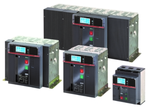
Emax 2 Circuit Breaker Ratings

[1] IEEE C37.20.10 – 2016, IEEE Standard Definitions for AC (52 kV and below) and DC (3.2 kV and below) Switchgear Assemblies [2] IEEE C37.20.1 – 2015, IEEE Standard for Metal-Enclosed Low-Voltage (1000 Vac and below, 3200 Vdc and below) Power Circuit Breaker Switchgear [3] ANSI C37.50 – 2018, Low Voltage AC Power Circuit Breakers Used in Enclosures— Test Procedures [4] ANSI C37.51 – 2018, Metal-Enclosed Low-Voltage AC Power Circuit Breaker Switchgear Assemblies— Conformance Test Procedures [5] UL 1066, Fourth Edition, Low-Voltage AC and DC Power Circuit Breakers Used in Enclosures
Related Content
Check out more on power circuit breakers: Emax 2 circuit breakers on ABB website
Presented by:
This site is created by ABB application engineers and experts as an educational tool to help engineers.

- Get custom product tools and services
- Access training
- Manage support cases
- Create and manage your orders (authorized partners only)
Schneider Electric USA Website
Search FAQs
Per the nec, what are the standard ampere ratings of fixed-trip circuit breakers (600vac maximum), released for: schneider electric usa.
Discuss this topic with experts
Start here!
Find answers now. Search for a solution on your own, or connect with one of our experts.
Contact Support
Reach out to our customer care team to receive more information, technical support, assistance with complaints and more.
Where to buy?
Easily find the nearest Schneider Electric distributor in your location.
Search topic-related frequently asked questions to find answers you need.
Contact Sales
Start your sales inquiry online and an expert will connect with you.
Circuit Breaker Ratings and Specifications | Circuit Breaker Nameplate
This article covers different circuit breaker ratings (voltage rating, frequency rating, frame rating, continuous current rating, short circuit current rating, fuse rating, control voltage rating, and megavolt ampere rating, ) and its specifications. it also discusses circuit breaker nameplate details. .
A circuit breaker is an electrical device that opens and closes a circuit by non-automatic means and automatically opens a circuit when a predetermined current overload is reached, without damage to itself. Circuit breakers protect circuits , and their function is similar to fuses.
A fuse is an electrical overcurrent protective device with a fusible portion that is heated and broken by the passage of excessive current.
The difference between circuit breakers and fuses is that circuit breakers can be reset and used repeatedly. In contrast, fuses must be replaced once they have been opened (blown) from an overcurrent condition.
An overcurrent protective device (OCPD) is a circuit breaker, fuse, or switch with an element that disconnects or discontinues current flow when the amount of current exceeds the design load. An OCPD is also known as a trip device.
Circuit breaker original equipment manufacturers (OEMs) design and build products with various ratings that must not be exceeded. Exceeding these ratings can cause catastrophic failure with resulting damage to nearby equipment as well as injury or death.
Circuit breaker ratings are determined by the National Electrical Manufacturer’s Association (NEMA) and the Institute of Electrical and Electronics Engineers.
NEMA is a trade organization that follows ANSI guidelines for the development of its standards. Usually, all members that develop and vote on a NEMA standard are OEMs.
The Institute of Electrical and Electronics Engineers (IEEE) is a professional association that is dedicated to advancing technological innovation and excellence of electrical and electronic equipment.
As defined in IEEE C37.100 , a circuit breaker is “A mechanical switching device, capable of making, carrying, and breaking currents under normal circuit conditions and also, making and carrying for a specified time and breaking currents under specified abnormal circuit conditions such as those of short circuit.”
According to Article 100 of the NEC® , a circuit breaker is “A device designed to open and close a circuit by non-automatic means, and to open the circuit automatically on a predetermined overcurrent without damage to itself when properly applied within its rating.”
IEEE Standard C37.16 covers circuit breaker ratings, application, and operating conditions for low-voltage power circuit breakers. Circuit breaker ratings, application, and operating conditions for high-voltage power circuit breakers are contained in IEEE Standard C37.04.
It should be noted that the NEC® definition states that a circuit breaker will open a circuit “without damage to itself when properly applied within its rating.” Consequently, a circuit breaker could fail if it is applied outside of its rating. Therefore, it is important to ensure that circuit breakers are properly applied within their ratings as specified on the nameplate located on the circuit breaker.
A nameplate is a metal plate attached to a device, such as a circuit breaker, that lists its technical specifications. See Figure 1 . The circuit breaker ratings most commonly referred to are voltage, frequency, frame, continuous current, short-time current, short-circuit current, fuse, control voltage, and megavolt ampere (MVA) ratings.

Figure 1. It is important to ensure that circuit breakers are properly applied within their ratings as specified on the circuit breaker nameplate.
Voltage Rating
According to IEEE Standard C37.13, “The rated maximum voltage of a circuit breaker is the highest RMS voltage , three-phase or single-phase, at which it is designed to perform. The circuit breaker shall be rated at one or more of the following maximum voltages: 635 V, 508 V, or 254 V. For fused circuit breakers, the 635 V rated maximum voltage becomes 600 V to match the fuse rating.”
The voltage rating of a circuit breaker is the maximum continuous voltage that can be applied to the circuit breaker without causing a dielectric failure of its insulation. Often a circuit breaker has more than one voltage listed on its nameplate. The actual voltage rating of the circuit breaker is the highest voltage listed on the nameplate.
Maximum DC Voltage ratings are often less than the AC ratings. Circuit breaker poles in series are usually required in order to obtain the published DC ratings.
Frequency Rating
According to IEEE Standard C37.13 , “The rated frequency of a circuit breaker is the frequency at which it is designed to perform. The standard frequency is 60 Hz. Application at other frequencies should receive special consideration”.
Circuit breakers are typically rated at 50 Hz or 60 Hz and are sometimes rated for use in direct current (DC) systems. One special consideration for using circuit breakers at other frequencies is that the continuous current rating of 60 Hz circuit breakers applied to DC systems is often decreased, sometimes by as much as 20%. This is due to DC being more difficult to interrupt than alternating current (AC) during short-circuit conditions.
Frame Rating
The frame rating is the continuous current rating of all current-carrying parts of a low-voltage circuit breaker, excluding its OCPD. This includes the primary disconnects or stabs, contact assemblies, and any other parts that carry current.
The OCPD, also known as a trip unit, is not included because it may have a rating lower than the frame rating of the circuit breaker. When the rating of the OCPD is less than the frame rating, it becomes the continuous current rating of the circuit breaker. For example, many electrical drawings show low-voltage circuit breakers rated as “1600 A-Frame” and “800 A Trip.” This type of rating indicates that the current-carrying components of a circuit breaker can carry up to 1600 A of current continuously but that the OCPD will operate whenever the current through it exceeds 800 A.
Continuous Current Rating
According to IEEE Standard C37.13 , “The rated continuous current of a circuit breaker is the designated limit of RMS current at a rated frequency that it shall be required to carry continuously without exceeding the temperature limitations.
The preferred continuous current ratings of the various frame sizes are listed in ANSI C37.16. The rated continuous current of a circuit breaker equipped with direct-acting trip devices or fuses of a lower rating than the frame size of the circuit breaker is determined by the rating of those devices.”
Another way to define continuous current is that it is the amount of current a device can carry without exceeding its rated temperature rise over a set period of time. As current flows through a conductor, it creates heat. This is often referred to as copper loss (I 2 R).
As current flow through a conductor increases, the heat generated by copper loss also increases. At some point, the heat created by the current flow can be enough to cause thermal damage to the surrounding insulation. Most electrical devices have a rated temperature rise of 40°C (104°F) that is based on the thermal characteristics of the device insulation.
The methodology used in evaluating the electrical insulation thermal characteristics can be referenced in IEEE Standard 1, Section 7, IEEE Recommended Practice—General Principles for Temperature Limits in the Rating of Electrical Equipment and for the Evaluation of Electrical Insulation.
The rated temperature rise is the temperature rise of an electrical device or component above ambient, or surrounding air, temperature. For example, if the temperature of a device is 65°C (149°F) and the ambient temperature is 30°C (86°F), the temperature rise would be 35°C. Using this basis excludes the effects of ambient temperature and focuses on the actual temperature of the device or component. The second sentence in this definition refers to the “preferred continuous current ratings”.
IEEE Standard C37.16, Low-Voltage Power Circuit Breakers and AC Power Circuit Protectors — Preferred Ratings, Related Requirements, and Application Recommendations, provides recommended combinations of circuit breaker frame size, OCPD ratings, and voltage ratings. The third sentence of the standard is true for all circuit breakers, not just direct-acting OCPDs or fuses. “The rated continuous current of a circuit breaker equipped with direct-acting trip devices or fuses of a lower rating than the frame size of the circuit breaker is determined by the rating of those devices.” A direct-acting OCPD is also referred to by the IEEE as an electromechanical or series OCPD. Most series OCPDs were of an oil dashpot design, although Westinghouse manufactured an air dashpot device. These direct-acting OCPDs were connected in series with the load current. When they operated, they physically caused the circuit breaker to open by operating the trip bar. As with circuit breakers, series OCPD ratings can be identified by their nameplates. See Figure 2.

Figure 2. An OCPD (trip device) can be identified by its nameplate.
The actual continuous current rating of a low-voltage circuit breaker is always determined by the rating of its OCPD. The continuous current rating cannot exceed the frame rating of the circuit breaker but can be equal to it for a low-voltage power circuit breaker.
For example, a Westinghouse/Cutler- Hammer DS circuit breaker may have a 2000 A-frame rating while the OCPD may only have a rating of 1200 A. A molded-case circuit breaker can have a continuous current rating that is only 80% of its frame rating. Molded-case circuit breakers are typically smaller than other types of circuit breakers and have enclosed cases. This construction limits the amount of airflow through them.
The DS-style circuit breaker used in this example has a solid-state OCPD and uses current sensors to set the continuous current rating. This allows one circuit breaker to have several continuous current ratings by setting the taps on the current sensor to the appropriate value. Current sensors can be single-tap or multiple taps, depending on how the circuit breaker is ordered.
Note: An ITE K1600 circuit breaker with a 1600 A-frame rating could have either an electronic OCPD or a series OCPD (OD-3, OD-4, or OD-5). With a series OCPD, the continuous current rating would be determined by the coil rating of the OCPD. For the example 1600 A-frame ITE circuit breaker, ITE listed coil ratings from 300 A to 1600 A. Unlike the electronic OCPD, which may have several continuous current ratings by using a multi-tap sensor, the series OCPD would only have the one rating based on its coil rating.
IEEE Standard C37.06.5.3.1 provides the following conditions on which continuous current ratings are based:
- Circuit breakers are used under usual service conditions.
- The total temperature limits of the materials used for circuit breaker parts shall be considered. A temperature rise reference is given to permit testing at reduced ambient temperature. • Circuit breakers designed for installation in enclosures shall meet these ratings when in their proper enclosure and based on 40°C ambient temperature outside the enclosure.
- Outdoor circuit breakers and indoor circuit breakers without enclosures shall have ratings based on 40°C ambient temperature.
Most series-type OCPDs have a range of minimum pickup settings from 80% to 160% of the continuous current rating. Newer solid-state and digital OCPDs can have minimum pickup settings that range from 50% to 120%. Settings above 100% of the continuous current rating do not increase the amount of current the device can safely carry but are used to compensate for transient overcurrent conditions. For example, an electric motor that has an extra-long startup time could cause a circuit breaker set at 100% to a false trip. By increasing the minimum pickup to 140%, the motor would be able to start as designed. The primary problem with this easy fix is that the OCPD acts as if it has a higher continuous current rating than it actually does.
Never set series-type OCPDs above 100% of their maximum continuous current rating without having an engineer review effects on the electrical power systems.
Short-Time Current Ratings
The short-time current rating of a circuit breaker is the maximum current it can safely carry for two 0.5 sec periods, with a 15 sec rest period between them at zero current.
According to IEEE Standard C37.13, “For an unfused circuit breaker, the rated short-time current is the designated limit of available (prospective) current at which it shall be required to perform its short-time current duty cycle (two periods of 1⁄2 s current flow, separated by a 15 s interval of zero current) at rated maximum voltage under the prescribed test conditions. This current is expressed as the RMS symmetrical value of current measured from the available current wave envelope at a time 1⁄2 cycle after short-circuits initiation.”
Note: Current-limiting fuses do not have a rated short-time current. Only the circuit breaker element of the fused circuit breaker assembly can have such a rating.

Electrical equipment is provided with overcurrent protection to protect it from high currents caused by overloads and short circuits.
Short-Circuit Current Ratings
According to IEEE Standard C37, “The rated short-circuit current of an unfused circuit breaker is the designated limit of available (prospective) current at which it shall be required to perform its short-circuit current duty cycle (0 – 15 s – CO) at the rated maximum voltage under the prescribed test conditions. This current is expressed as the RMS symmetrical value of current measured from the available current wave envelope at a time 1/2 cycle after short-circuit initiation. Unfused circuit breakers shall be capable of performing the short- circuit current duty cycle with all degrees of current asymmetry produced by three-phase or single-phase circuits having a short-circuit power factor of 15% or greater (X/R ratio of 6.6 or less).”
The short-circuit current rating, also known as the interrupting rating, is the maximum short-circuit current a circuit breaker can safely clear without external damage. External damage is specified since there will probably be some internal damage, such as erosion of the arcing contacts, carbon and other arcing by-products scattered inside the arc chutes, and thermal damage to the insulation system, due to the extremely high temperatures of the arc interruption process. However, there will be no external damage, and the circuit breaker should still be serviceable. The circuit breaker should be inspected after an arc interruption.
According to IEEE Standard C37.13, “Unfused circuit breakers with direct-acting instantaneous phase trip elements shall have short-circuit current ratings at each rated maximum voltage.” It is common for OEMs to state the short-circuit current ratings of their OCPDs at standard system voltage levels. See Figure 3. As the system voltage increases and the arc becomes more persistent and difficult to extinguish, the rating often has to be decreased.

Figure 3. The short-circuit current rating is the maximum short-circuit current a circuit breaker can safely clear without being damaged externally. It is usually listed on the circuit breaker nameplate.
Fuse Ratings
Certain types of circuit breakers are protected by current-limiting fuses. A circuit breaker that uses current-limiting fuses will not have an interrupting rating but will use the interrupting rating of the fuse. By standard, current-limiting fuses must operate in half a cycle or less, although most fuse OEMs state that their fuses typically operate in a quarter of a cycle.
According to IEEE Standard C37.13, “The rated short-circuit current of a fused circuit breaker is the designated limit of available (prospective) current at which it shall be required to perform its short-circuit current duty cycle at the rated maximum voltage under the prescribed test conditions. The short-circuit current duty cycle consists of an O (OPEN) followed by a CO (CLOSE – OPEN) operation. The time between the O and CO operations is the time necessary to replace fuses and to reset the open-fuse trip device. This current is expressed as the rms symmetrical value of current measured from the available current wave envelope at a time 1⁄2 cycle after short-circuiting initiation.
Fused circuit breakers shall be capable of performing the short-circuit current duty cycle with all degrees of current asymmetry produced by three-phase or single-phase circuits having a short-circuit power factor of 20% or greater (X/R ratio of 4.9 or less).”
Control Voltage Ratings
According to IEEE Standard C37.13, “The rated control voltage is the voltage at which the mechanism of the circuit breaker is designed to operate when measured at the control power terminals of the operating mechanism with the highest operating current flowing. Rated control voltages and their ranges for low-voltage power circuit breakers are listed in Table 23 of ANSI C37.16.”
Coils, latches, motors, and other electrical components used to control a circuit breaker use lower voltage for the control circuit operation, most often DC voltage. Typical control voltages are 24 VDC, 48 VDC, 125 VDC, and 250 VDC. Less frequently, 120 VAC, 240 VAC, and 460 VAC are used. Some circuit breakers may have both AC and DC voltages of different nominal ratings. Control power will be brought into the circuit breaker through the secondary disconnects.
Megavolt Ampere Ratings
The short-circuit capability of oil, gas, and some older models of air circuit breakers is rated in megavolt amperes rather than or in addition to short-circuit current. A megavolt ampere (MVA) rating is the rated voltage times the rated interrupting current of a circuit breaker. Common examples are circuit breakers rated 250 MVA, 500 MVA, and 1500 A. MVA ratings for circuit breakers can be located in OEM manuals or on the nameplates. See Figure 4.

Figure 4. The short-circuit capability of some types of circuit breakers is rated in megavolt amperes (MVA) rather than in short-circuit current.
- Site Search Search Posts Find A Forum Thread Number Threads by Name Search FAQs
- ENGINEERING.com
- Eng-Tips Forums
- Tek-Tips Forums
Join Eng-Tips ® Today!
Join your peers on the Internet's largest technical engineering professional community. It's easy to join and it's free.
Here's Why Members Love Eng-Tips Forums:
- Notification Of Responses To Questions
- Favorite Forums One Click Access
- Keyword Search Of All Posts, And More...
Register now while it's still free!
Already a member? Close this window and log in.
Join Us Close
Ampere rating of a circuit, feeder, or service – what is it based on?

After writing articles for quite a few years, I got used to numerous questions that the readers sent to me.
But I’m a bit surprised by a number of questions that were sent to me in relation to the fundamentals of the safety criteria prescribed by the Canadian Electrical Code, Part I ( CE Code ).
So, let’s try to clarify the subject indicated in this article’s title by posing five relevant questions and answers in conjunction with this subject.
Question 1. What is the rating of a branch circuit, feeder, or consumer’s service?
Answer 1. Subrule 8-104(1) of the CE Code describes a circuit (feeder or consumer’s service) rating as follows:
“ 8-104 Maximum circuit loading (see Appendix B)
1) The ampere rating of a consumer’s service, feeder, or branch circuit shall be the ampere rating of the overcurrent device protecting the circuit or the ampacity of the conductors, whichever is less .”
This description means that a rating of a typical branch circuit is a selected rating or setting of the overcurrent device that protects the branch circuit or ampacity of circuit conductors, whichever happened to be less. It means that (for example) if a 200 A-rated overcurrent device is selected to protect a branch circuit, and # 4/0 copper conductors intended for installation in a raceway are selected from the 75 ° C column of Table 2 of the CE Code, with an assigned ampacity of 230 A to such conductors, then the ampere rating of such branch circuit is 200 A .
Question 2. What is the relationship between the rating of a branch circuit and the load connected to that branch circuit?
Answer 2. Subrule 8-104(2) of the CE Code offers the following statement:
“ 2) The calculated load in a circuit shall not exceed the ampere rating of the circuit .”
This CE Code requirement means that under no condition, calculated load in the branch circuit (feeder or consumer’s service) is allowed to exceed the rating of that branch circuit (feeder or consumer’s service). It means that in our example above, the calculated load in a 200 A-rated branch circuit cannot exceed 200 A.
Question 3. Can the calculated load be equal to the rating of the circuit?
Answer 3. Subrules 8-104(5) and (6) of the CE Code provide a comprehensive answer to this question as follows:
“ 5) Where a fused switch or circuit breaker is marked for continuous operation at 100% of the ampere rating of its overcurrent devices, the continuous load as determined from the calculated load shall not exceed the continuous operation marking on the fused switch or circuit breaker and
- a) except as required by Item b), shall not exceed 100% of the allowable ampacities of conductors selected in accordance with Section 4; or
- b) shall not exceed 85% of the allowable ampacities of single conductors selected in accordance with Section 4.
6) Where a fused switch or circuit breaker is marked for continuous operation at 80% of the ampere rating of its overcurrent devices, the continuous load as determined from the calculated load shall not exceed the continuous operation marking on the fused switch or circuit breaker and
- a) except as required by Item b), shall not exceed 80% of the allowable ampacities of conductors selected in accordance with Section 4; or
- b) shall not exceed 70% of the allowable ampacities of single conductors selected in accordance with Section 4 .”
The above-stated Code requirements mean that if a fused switch or circuit breaker is marked for continuous operation at 100% of the ampere rating of its overcurrent devices , the continuous load as determined from the calculated load is not allowed to exceed the continuous operation marking (i.e., 100%) on the fused switch or circuit breaker. It means that if in accordance with our example above, the 200 A-rated circuit breaker is marked for continuous operation at 100% of the ampere rating of its overcurrent devices, the continuous load of such branch circuit is allowed to be as high as 200 A.
If, however, in accordance with our example above, the 200 A-rated circuit breaker is marked for continuous operation at 80% of the ampere rating of its overcurrent devices , the continuous load of such branch circuit is not allowed to exceed 160 A.
The requirement also means that when multi-conductor cables or conductors in raceways are used in an electrical installation, the ampacity of such selected conductors also cannot exceed the continuous operation marking on the fused switch or circuit breaker. In our example above, selection of conductors with an assigned ampacity of 200 A would be sufficient if the 200 A-rated circuit breaker is marked for continuous operation at 100% of the ampere rating of its overcurrent devices, and the continuous load of such branch circuit is as high as 200 A. If, however, in accordance with our example above, the 200 A-rated circuit breaker is marked for continuous operation at 80% of the ampere rating of its overcurrent devices, selection of conductors with an assigned ampacity of 200 A would be allowed if the continuous load of such branch circuit does not exceed 160 A.
The above-stated CE Code requirements also mean that when single-conductors are used in electrical installations, loads connected to such conductors cannot exceed:
(a) 85% of the allowable ampacities of single conductors selected in accordance with Section 4, if a fused switch or circuit breaker is marked for continuous operation at 100% of the ampere rating of its overcurrent devices; or
(b) 70% of the allowable ampacities of single conductors selected in accordance with Section 4, if a fused switch or circuit breaker is marked for continuous operation at 80% of the ampere rating of its overcurrent devices.
Thus, in our example above, if single conductor cables are utilized in an electrical installation in accordance with applicable provisions of Rule 4-004 of the CE Code, then selection of single conductors with an assigned ampacity of 235.29 A would be necessary if the 200 A-rated circuit breaker is marked for continuous operation at 100% of the ampere rating of its overcurrent devices, and the continuous load of such branch circuit is as high as 200 A. If, however, as per our example above, the 200 A-rated circuit breaker is marked for continuous operation at 80% of the ampere rating of its overcurrent devices, selection of single conductors with an assigned ampacity of at least 228.57 A would be required, if the continuous load of such branch circuit does not exceed 160 A.
Question 4: If all conductors and cables used in an electrical installation have an insulation temperature rating of 90 ° C, why is it required to de-rate such conductors using the 75 ° C temperature column, as indicated in answer to question 1?
Answer 4. When 90 ° C rated conductors are used in electrical installations and are terminated at the electrical equipment marked with the maximum termination temperature, their selected ampacity must ensure that at the termination point, temperature generated by such selected conductors does not exceed temperature limitations marked on the equipment. Rule 4-006 of the CE
Code elaborates on this condition as follows:
“ 4-006 Temperature limitations (see Appendix B)
1) Where equipment is marked with a maximum conductor termination temperature, the minimum size of conductor used shall be based on the allowable ampacity in the temperature column in Table 1, 2, 3, or 4, with all relevant correction factors being applied as required by Rule 4-004, corresponding to the maximum termination temperature marked on the equipment.
2) For the purpose of Subrule 1), and except as provided for by other Rules of this Code, where the maximum conductor termination temperature for equipment is not marked, the maximum conductor termination temperature shall be considered to be
- a) 60°C for equipment
- i) rated not more than 100 A; or
- ii) marked for use with No. 1 AWG or smaller conductors; and
- b) 75°C for equipment
- i) rated more than 100 A; or
- ii) marked for use with conductors larger than No. 1 AWG.
3) Notwithstanding Subrule 2), for high-voltage equipment where conductor termination temperatures are not marked, it shall be permitted to consult the manufacturer to establish the permitted termination temperature.
4) Subrules 1) and 2) shall apply only to the first 1.2 m of conductor length measured from the point of termination on the equipment.
5) Where a cable transition is made to meet the requirements of Subrule 1) or 2), the length of a conductor terminating on equipment shall be not less than 1.2 m.
6) Where the conductor ampacity is selected from Tables D8A to D11B, Tables D17A to D17N, or Table 12E, Subrules 1) and 2) shall apply. ”
Therefore, if in our example above, as indicated in answer 1, a 200 A-rated circuit breaker is marked for maximum termination temperature at 75 ° C ampacity of such 90 ° rated conductors intended for installation in a raceway, would have to be selected not from 90 ° Column of Table 2 of the CE Code, but from 75 ° C column – to comply with temperature limitation requirements of Rule 4-006 of the CE Code.
Question 5: Are there any other potential requirements in the CE Code, which would “force” reduction of the ampacity of the selected conductors and “force” upsizing of such conductors for the purpose of accommodating calculated load?
Answer 5: Subrule 4-004(7) of the CE Code mandates the use of correction factors, which might further reduce the ampacity of selected conductors under the following conditions:
“ 7) The correction factors specified in this Rule
- a) shall not apply to conductors installed in auxiliary gutters containing 30 conductors or less; and
- b) shall apply only to power and lighting conductors as follows:
- i) the ampacity correction factors of Table 5A, where conductors are installed in an ambient temperature exceeding or anticipated to exceed 30 °C;
- ii) the ampacity correction factors of Table 5B, where single-conductor cables are installed in free air in accordance with Subrule 9);
iii) the ampacity correction factors of Table 5C, where single-conductor cables are installed in free air, single conductors are installed in totally enclosed non-ventilated raceways, or multi-conductor cables are installed in ventilated and ladder-type cable trays or in nonventilated cable trays in accordance with Subrule 1) c), 2) c), 11), 12), 13), 23), or 25), as applicable; and
- iv) the ampacity correction factors of Table 5D, where single-conductor cables are installed in free air or single-conductor or multi-conductor cables are installed in ventilated and ladder-type cable trays in accordance with Subrule 8) or 24), as applicable .”
As it could be seen from the referenced Subrule 4-004(7) above, specific conditions of the installation may trigger additional requirements for ampacity reduction of selected conductors. For example, if selected conductors are intended to be installed in an ambient temperature exceeding 30 ° C, then correction factors required by Table 5A would have to apply.
Where single conductor cables are intended for installation in free air in accordance with Table 1 or table 3 of the CE Code, and there are from two to four single conductor cables present and spaced less than 25% of the largest cable diameter, then provisions of Table 5B, would be warranted for application.
If more than three conductors are installed in accordance with Tables 2 and 4 of the CE Code, then correction factors mandated by Table 5C would have to be applied – to further reduce ampacity (and to further increase size) of already selected conductors.
If conductors are intended for installation in ventilated and ladder-type cable trays, then additional current rating correction factors could be necessary in accordance with Table 5D.
And finally, the size of conductors might have also to be increased – to comply with voltage drop requirements of Rule 8-102 of the CE Code.
Hopefully, this brief illustration of the CE Code requirements is helpful in the determination of the ampere rating of a branch circuit, feeder, or service.
And as always, local electrical safety regulators should be consulted regarding specific conditions of the intended installation.

Air-Conditioning Equipment Installations

Basic three-phase power measurements explained

Safety in Marinas

Find Us on Socials
Let’s take a look at the differences between calculated loads, demand loads, demonstrated loads, and the application of demand factors in the CE Code.
Emergency lighting – What, Why, and How?
Let’s take a look at eight recent questions regarding Canadian provisions for emergency lighting.

Mitigating household electrical risks through better appliance design and improved safety standards
Ongoing improvements to the safety standards for electrical appliances are reducing the likelihood of threats to children and improving the outlook for safety in our homes.
Online Calculators and Tables to Help You Determine Proper Wire Size
Electrical current is measured in amps. Each wire size, or wire gauge (AWG), has a maximum current limit that a wire can handle before damage occurs. It is important to pick the correct size of wire so that the wire doesn't overheat.
The number of devices connected to the circuit usually determines how much current will flow through the wire.
The wire size chart below shows allowable ampacities of insulated conductors rated up to and including 2000 Volts, 60°C through 90°C (140°F through 194°F), not more than three current-carrying conductors in raceway, cable, or earth (directly buried), based on ambient air temperature of 30°C (86°F).
Search Amazon for your Electrical products such as wire, tools, extension cords, and accessories.
Wire Size Chart and Maximum Amp Ratings
Note: View additional wire size charts from the list below.
For ambient temperatures other than 30°C, Correction Factors must be taken into consideration.
Visit the Terms of Use and Privacy Policy for this site. Your feedback is greatly appreciated. Let us know how we can improve.
Link Navigation
- Wire Size Chart
- Calculator List and Descriptions
- Wire Size Calculator
- Advanced Wire Size Calculator
- Wire Ampacity Calculator
- Advanced Wire Ampacity Calculator
- Arc Flash Calculator
- Voltage Drop Calculator
- Circuit Distance Calculator
- Ohm's Law Calculator
- Motor Wire Size Calculator
- Ground Wire Size Calculator
- Distance Between Conduit Supports Calculator
- Resistor Color Code Calculator
- Time Overcurrent Relay Operate Time Calculator
- Table List and Descriptions
- Maximum Wire Ampacity for Current-Carrying Conductors in Raceway 30°C Table
- Maximum Wire Ampacity for Current-Carrying Conductors in Free Air 30°C Table
- Maximum Wire Ampacity for Current-Carrying Conductors in Raceway 40°C Table
- Maximum Wire Ampacity for Current-Carrying Conductors in Free Air 40°C Table
- Full-Load Current for Three-Phase AC Motors Table
- Three-Phase AC Motor Wire Sizes and Circuit Protection Table
- Arc Flash Tables
- Ground Conductor Size Table
- Distance Between Rigid Conduit Supports Table
- Wire Ampacity Correction Factors Table

Sizing A Circuit Breaker: Breaker Size Calculator + Amp Chart
Sizing a circuit breaker is never easy. But it’s also not all that difficult . Everybody knows that we need an adequately sized circuit breaker that allows for sufficient electric current. If we undersize a breaker, the breaker will likely catch on flame. No pressure here.

How do you go about picking the correct circuit breaker size? Do you need a 10A, 15A, 20A, 30A, 40A, 50A breaker, etc?
Standard breaker sizes are 15A, 20A, 25A, 30A, 35A, 40A, 45A, 50A, 60A, 70A, 80A, 90A, 100A, 110A, 125A, 150A, 175A, 200A, 225A, 250A, 300A, 350A, 450A, 500A, 600A, 700A, 800A, 1000A, 1200A, 1600A, 2000A, 2500A, 3000A, 4000A, 5000A, and 6000A.
Sizing a circuit breaker is actually quite easy. You just need to know a couple of rules. These are:
- 80% NEC breaker rule. This is the most basic NEC (National Electric Code) rule that states that you can’t push the current over 80% of its specified ampacity. Example: If you have a 20 amp breaker, you can only allow for a 16A current. 16A is 80% of the max. the specified ampacity of the circuit breaker. This is a safety measure; you better have a bit of overhead to prevent the circuit from frying. You can read the full Article 240.4(B) in NEC 2014 on this here .

If you know how to calculate the amps and account for the 80% breaker rule, you can calculate the size of the breaker yourself.
To help everybody sizing these breakers out, we will explain how to determine the right size of a breaker. On top of that, we include a Circuit Breaker Size Calculator further on (just insert watts and volts, and you get the correct breaker size).
At the end, we also included the ‘just tell me the breaker size I need’ Breaker Size Chart that tells you what breaker size you need for devices with different wattages (from 50W units to big 20,000W devices).
Let’s look at how breaker size can be calculated manually (you can also use the calculator or/and chart below):
Table of Contents
How To Calculate Size Of A Circuit Breaker?
This is the easiest to explain with an example.
Let’s say that we have a simple 1,500-watt space heater running on a standard 120V circuit. What size amp breaker do you need for a 1,500-watt space heater?
First, you need to calculate how many amps does this heater draw like this:
Current (Amps) = Power (Watts) / Voltage (Volt)
In our situation this is:
Current = 1,500W / 120V = 12.5 Amps
Now we know that the 1,500W space heater draws 12.5 amps. We have to account for the 80% breaker rule. This means that these 12.5 amps should represent 80% of the breaker amps. To calculate the size of the circuit breaker needed, we have to multiply the amp draw by 1.25 factor like this:
Minimum Circuit Breaker Size = 12.5A × 1.25 = 15.63 Amps
We can’t use a 15A breaker because the breaker ampacity should be at least 15.63A. The next breaker size is 20 amps; that means we need to use a 20A breaker for a 1,500W space heater running on 120V standard circuit.

Here is the basic step-by-step procedure we did to determine the size of a circuit breaker:
- Calculate the amp draw. We use the basic electric power equation for this. If we know the wattage and voltage, we can quite easily calculate the amp draw.
- Multiply amp draw by 1.25 to account for the 80% breaker rule. The resulting amps are the minimum ampacity a correctly sized circuit breaker should have.
- Choose a circuit breaker size. We usually pick between 10A, 15A, 20A, 25A, 30A, 35A, 40A, 50A, 60A circuit breakers, and so on.
This is how breaker sizing is done manually. The easiest way is to use a dynamic calculator. You simply input that wattage and the voltage, and the calculator will tell you what is the minimum size of a circuit breaker you need. You can use this calculator here:
Circuit Breaker Size Calculator
Here is how this breaker sizing calculator works:
Let’s say you have a big 5,000W air conditioner (this is usually a 5-ton unit). It runs on a 220V circuit. What size circuit breaker do you need?
Just slide the wattage slider to ‘5000’ and voltage slides to ‘220’ and you get ‘28.41 Amps’. Therefore you need a circuit breaker with at least 28.41A ampacity. 25A breaker is too small; you need a 30A breaker .
You can do this for literally any device running on any voltage. You can also play around with numbers to see how the amps change.
If you want the ‘just tell me the circuit breaker I need’ you can consult this chart:
Breaker Size Chart (For 120V And 220V Circuits)
You just need to know the wattage of the device you need a circuit breaker for and you can check what size breaker you need if you run it on a standard 120V circuit or an upgraded 220V circuit:
As you can see, calculating what size breaker you need is not all that hard. Of course, with bigger amp draws, you can connect several 30A or 50A in parallel to increase the total breaker ampacity.
We hope this illustrates how everybody can figure out the size of circuit breaker they need. If you have any questions regarding this breaker sizing, you can use the comments below and we’ll try to help you out.
Related posts:
- 50 Amp Wire Size Details: Gauge, Breaker, 220/240V Example
- Thermostat Not Reaching Set Temperature: 7 Causes + Fixes
- Wire Gauge Wattage Charts For AWG Wires (4/0 AWG To 14 AWG)
- How Many Outlets On A 15 Amp, 20 Amp, 30 Amp Circuit? (NEC 210.21)
- Thermostat Wire Color Codes For 3-8 Wire Thermostats (Color-By-Color)
12 thoughts on “Sizing A Circuit Breaker: Breaker Size Calculator + Amp Chart”
Thank you, this is very help full.
very much help full
Excelente information. Thank you.
The most amazing easy method. very Helpfull.
Thank you, Imran, we try to simplify it as much as possible. It’s nice to see a bit of recognition.
Helpful. 1,500-watt space heater running on a standard 120V circuit. What size amp breaker do you need for a 1,500-watt space heater? how can I use 120 v circuit.
Hi Masum, alright, 1500W heater on 120V draws 1500W/120V = 12.5 amps. To apply the 80% rule, you have to multiply this current by 125% like this: 12.5A × 1.25 = 15.63 amps. So, a 15A breaker won’t cut it, but a 20A breaker will be great for a 1500-watt space heater on a 120V circuit. Hope this helps.
Hi I have a 1200 watt generator , the breaker has gone bad and there is no size printed on the breaker. Im not sure if you can calculate the size the same way you would for a AC unit. What size would you suggest ? Thanks
Hi Renald, the size of the breaker you need for a 1,200 watt generator really depends on the amps it will give out. You can calculate the amps if you know the voltage. Generators can have 12V DC, 24V DC, 110-120V AC, 240V AC voltages. Example: Let’s say your 1200W generator has a 24V DC voltage. You can calculate the amps like this: 1200W/24V = 50 Amps. This is the current in the wire. You can calculate the minimum required breaker size for this generator like this: 50 Amp × 1.25 = 62.5 Amps. In this case you can go for 70A breaker, or 3x30A breakers, since their capacity if north of 62.5 amps. Hope this helps.
This article is flawless thank you!
Great info! Much appreciated but I’m trying to determine what breaker or breakers I need for my bass boat. 3x 12V in series for my 36V trolling motor and 1x 12 V for my electronics and starting battery which also powers the various pumps and aerators. Any help would be greatly appreciated!
Hi Tom, the wattage you need is the key here. Electronics will have lower wattage but pumps and aerators… that should like high wattage stuff. Example: If you would put in 60A amp breaker on 36V voltage, and apply the 80% breaker rule, you will get 1,728W of power. It’s really hard to advise here without wattages but from the looks of it – 36V and energy-demanding pumps – the first presumption would be that you need big breakers, at least 60A. Hope this helps.
Leave a Comment Cancel reply
Save my name, email, and website in this browser for the next time I comment.
IMAGES
VIDEO
COMMENTS
Short-time pickup is adjustable from 1.5 to 10 times the trip unit ampere setting (Ir). For example, a 1000 ampere frame can be adjusted to trip anywhere from 1500 to 10,000 amps. The switch also has an "OFF" position to eliminate short-time pickup and short-time delay. Short-time pickup used for selective tripping.
240.6 (A) Fuses and Fixed-Trip Circuit Breakers. The standard ampere ratings for fuses and inverse time circuit breakers shall be considered as shown in Table 240.6 (A). Additional standard ampere ratings for fuses shall be 1, 3, 6, 10, and 601. The use of fuses and inverse time circuit breakers with nonstandard ampere ratings shall be permitted.
The standard ampere ratings for fuses and inverse time circuit breakers shall be considered as shown in Table 240.6 (A). Additional standard ampere ratings for fuses shall be 1, 3, 6, and 601. The use of fuses and inverse time circuit breakers with nonstandard ampere ratings shall be permitted.
The thermomagnetic trip unit consists of two parts: ... The nominal pickup point where a circuit breaker trip unit detects an overload is at 1.075 times the selected ampere rating. After the circuit breaker has picked up, it will not trip until the delay determined by the long-time delay adjustment has been achieved. 2. Neutral conductor protection
ampere rating, or 8 kA. For any fault current in excess of 8 kA, the ICCB with an external adjustment for the instantaneous trip element will trip with no intentional delay even though that device could have been applied with a 25 kA override instantaneous response. This is an important issue,because system coordination often is
to the largest ampere rating available in the group. The same frame size designation may be applied to more than one group of circuit breakers. 11 - GROUND-FAULT DELAY: an intentional time delay in the tripping function of a circuit breaker when a ground-fault occurs. 12 - GROUND-FAULT PICKUP SETTING: the nominal value of the ground-fault
(a) Rating or Setting of Overcurrent Protective Devices. The continuous ampere rating of a fuse shall not exceed three times the ampacity of the conductors. The long-time trip element setting of a breaker or the minimum trip setting of an electronically actuated fuse shall not exceed six times the ampacity of the conductor.
240.6 Standard Ampere Ratings. (A) Fuses and Fixed-Trip Circuit Breakers. The standard ampere ratings for fuses and inverse time circuit breakers shall be considered: 15, 20, 25, 30, 35, 40, 45, 50, 60, 70, 80, 90, 100, 110, 125, 150, 175, 200, ... Additional standard ampere ratings for fuses shall be 1, 3, 6, 10, and 601. 2/0 3/0 4/0 250 300 ...
The standard ratings in amperes for fuses and inverse time breakers are shown in Table 240.6 (A). The use of fuses and inverse time circuit breakers with nonstandard ampere ratings are permitted [Sec. 240.6 (A)]. Additional standard ampere ratings for fuses include 1, 3, 6, 10, and 601. Fuses rated less than 15A are sometimes required for the ...
Frame-size rating. A circuit breaker which can be fitted with overcurrent tripping units of different current level-setting ranges, is assigned a rating which corresponds to the highest current level-setting tripping unit that can be fitted. Example. A Compact NSX630N circuit breaker can be equipped with 11 electronic trip units from 150 A to ...
The interrupting capacity rating of an LVPCB is the rating of the circuit breaker with the instantaneous trip element activated or enabled. Anyone who applies a LVPCB without instantaneous trip elements would need to ensure that the short-time current rating of the device is greater than or equal to the available short-circuit fault current.
Issue: Where do circuit breaker amp ratings come from? Product Line: Circuit Breakers Resolution: Per NEC 240.6, the standard ampere rating for inverse time, fixed-trip circuit breakers, 600Vac maximum, shall be considered as follows:
It is often expressed in Amperes (A).A higher (AF) rating indicates a larger and more robust circuit breaker, capable of handling higher current loads without tripping. (AT) - Trip Unit Rating:
Amp Frame - Maximum continuous current carrying capacity for the thermal design of the circuit breaker. Amp Trip - either fixed or adjustablle device that limits the continuous rating of the device. Therefore the Amp Trip never exceeds the Amp Frame. 1.
The standard ampere ratings for fuses and inverse time circuit breakers shall be considered as shown in Table 240.6 (A). Additional standard ampere ratings for fuses shall be 1, 3, 6, and 601. The use of fuses and inverse time circuit breakers with nonstandard ampere ratings shall be permitted. Explore a searchable database of US construction ...
sizes from 400 to 5000 amperes. The 400-ampere-frame ICCB is typically the same size and cost as the 800-ampere frame but is equipped with smaller-ratio current sensors. PCBs are available in frame sizes from 800 to 5000 amperes. B. Short Circuit Ratings The short circuit rating of a circuit breaker is defined by its
A nameplate is a metal plate attached to a device, such as a circuit breaker, that lists its technical specifications. See Figure 1. The circuit breaker ratings most commonly referred to are voltage, frequency, frame, continuous current, short-time current, short-circuit current, fuse, control voltage, and megavolt ampere (MVA) ratings.
The amp trip will not go over the amp frame rating. The amp trip is what you use to size the trip rating of the breaker to protect down stream devices and cables. JTK . RE: Please Clarify the concept of Amp Frame and Amp Trip. jraef (Electrical) 25 Jan 06 19:24.
Answer 1. Subrule 8-104 (1) of the CE Code describes a circuit (feeder or consumer's service) rating as follows: " 8-104 Maximum circuit loading (see Appendix B) 1) The ampere rating of a consumer's service, feeder, or branch circuit shall be the ampere rating of the overcurrent device protecting the circuit or the ampacity of the ...
So for example you may see an MCP shown on a one-line diagram as "7A MCP", which means the continuous ampere rating of that breaker is 7A, and the magnetic trips will be adjustable from 300-1000%, so 21 to 70A. that is the way I read it 225 Amp Frame 125 Amp Trip (I assume thermal), instant ~12 times that.
The wire size chart below shows allowable ampacities of insulated conductors rated up to and including 2000 Volts, 60°C through 90°C (140°F through 194°F), not more than three current-carrying conductors in raceway, cable, or earth (directly buried), based on ambient air temperature of 30°C (86°F). Search Amazon for your Electrical ...
We have to account for the 80% breaker rule. This means that these 12.5 amps should represent 80% of the breaker amps. To calculate the size of the circuit breaker needed, we have to multiply the amp draw by 1.25 factor like this: Minimum Circuit Breaker Size = 12.5A × 1.25 = 15.63 Amps.